How to Use Adafruit KB2040 Kee Boar Driver: Examples, Pinouts, and Specs
Introduction
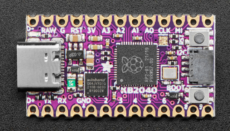
The Adafruit KB2040 Kee Boar Driver is a compact and versatile microcontroller board designed specifically for keyboard and input device applications. Powered by the RP2040 chip, it offers robust performance, USB-C connectivity, and compatibility with a wide range of input devices. Its small form factor and advanced features make it an excellent choice for custom keyboard projects, macro pads, and other human interface device (HID) applications.
Explore Projects Built with Adafruit KB2040 Kee Boar Driver
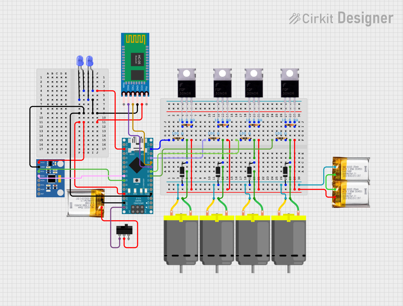

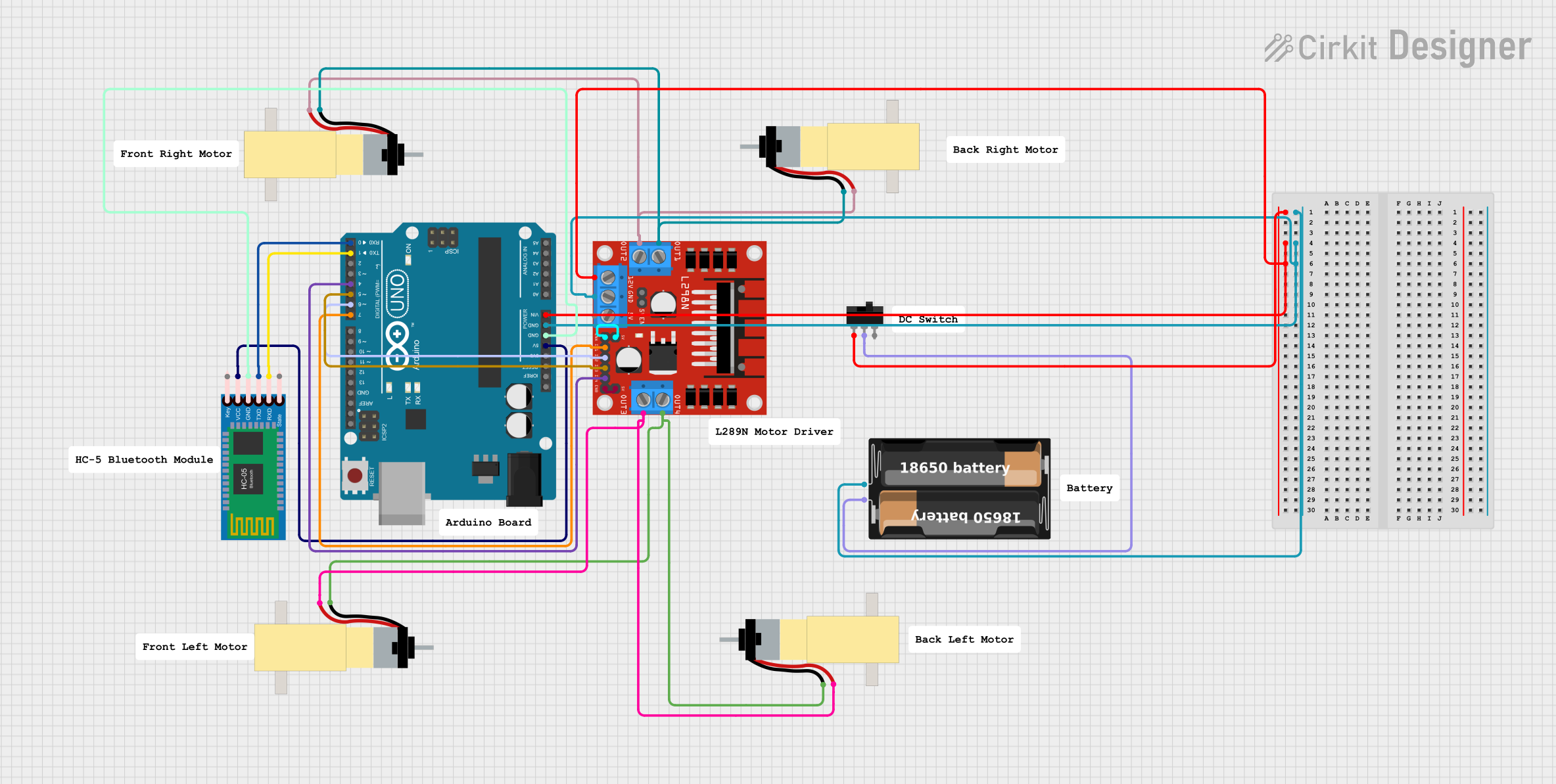
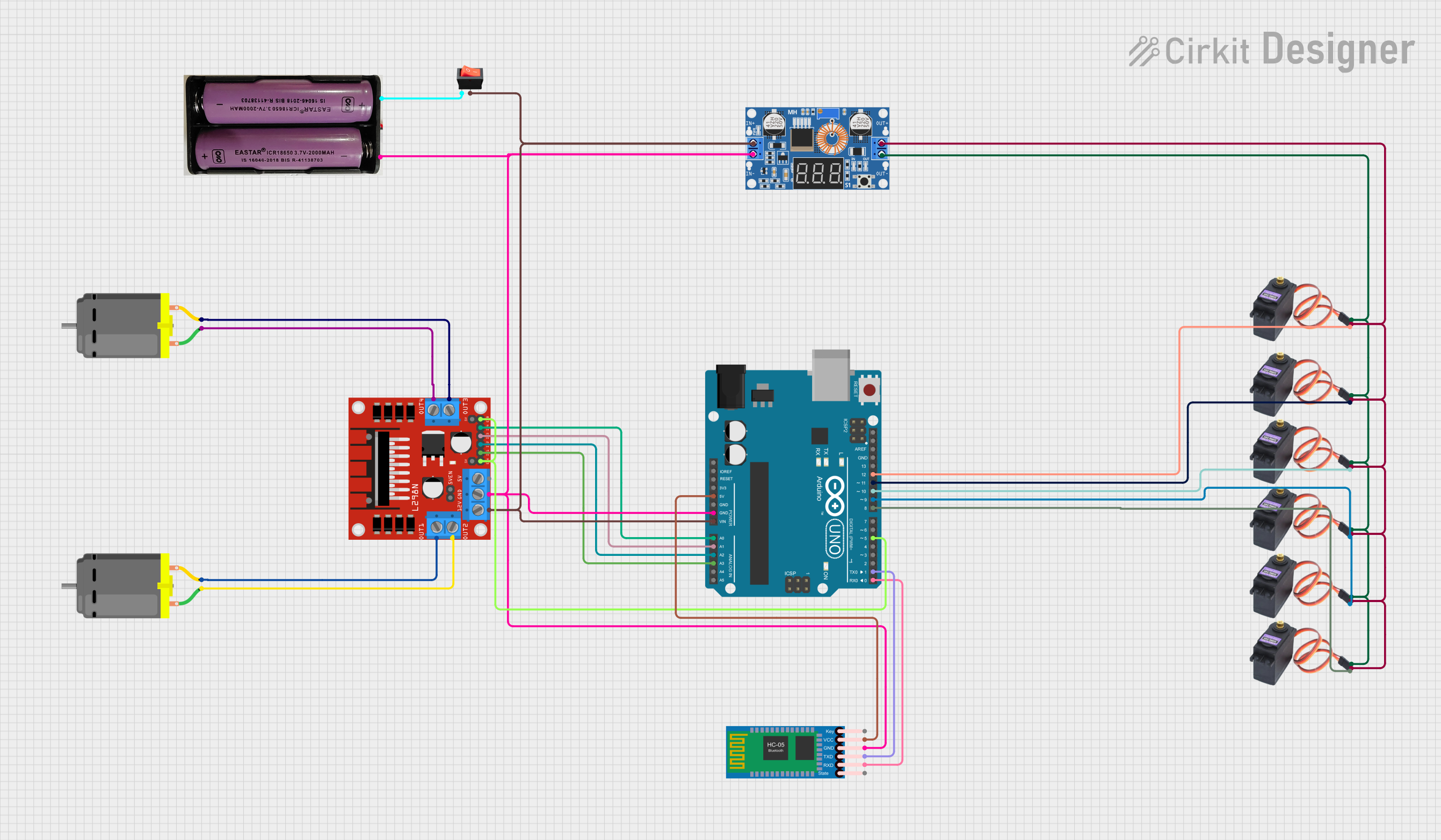
Explore Projects Built with Adafruit KB2040 Kee Boar Driver
Common Applications and Use Cases
- Custom mechanical keyboards
- Macro pads for productivity or gaming
- MIDI controllers and other musical input devices
- DIY human interface devices (HID)
- Prototyping and educational projects involving input/output devices
Technical Specifications
The Adafruit KB2040 Kee Boar Driver is built around the RP2040 microcontroller and includes several features tailored for keyboard and input device applications.
Key Technical Details
| Specification | Value |
|---|---|
| Microcontroller | RP2040 (Dual ARM Cortex-M0+ @ 133MHz) |
| Flash Memory | 8MB QSPI Flash |
| USB Connectivity | USB-C |
| GPIO Pins | 20 (4 with ADC support) |
| Input Voltage | 5V (via USB-C) |
| Logic Level | 3.3V |
| Current Draw | ~25mA (idle, without peripherals) |
| Dimensions | 51mm x 18mm x 4mm |
| Weight | 4g |
Pin Configuration and Descriptions
The KB2040 features 20 GPIO pins, which are accessible via solder pads. These pins can be used for digital I/O, analog input, and other functions. Below is the pinout description:
| Pin Number | Pin Name | Functionality |
|---|---|---|
| 1 | GND | Ground |
| 2 | 3V3 | 3.3V Power Output |
| 3 | A0 | Analog Input / GPIO |
| 4 | A1 | Analog Input / GPIO |
| 5 | A2 | Analog Input / GPIO |
| 6 | A3 | Analog Input / GPIO |
| 7 | D0 | Digital I/O / UART TX |
| 8 | D1 | Digital I/O / UART RX |
| 9 | D2 | Digital I/O |
| 10 | D3 | Digital I/O |
| 11 | D4 | Digital I/O |
| 12 | D5 | Digital I/O |
| 13 | D6 | Digital I/O |
| 14 | D7 | Digital I/O |
| 15 | D8 | Digital I/O |
| 16 | D9 | Digital I/O |
| 17 | D10 | Digital I/O |
| 18 | D11 | Digital I/O |
| 19 | D12 | Digital I/O |
| 20 | D13 | Digital I/O / Built-in LED |
Usage Instructions
How to Use the KB2040 in a Circuit
- Powering the Board: Connect the KB2040 to a USB-C power source. The board operates at 5V input and regulates it to 3.3V for internal use.
- Connecting Peripherals: Use the GPIO pins to connect switches, LEDs, or other input/output devices. Ensure that all connected devices operate at 3.3V logic levels to avoid damage.
- Programming the Board: The KB2040 supports CircuitPython, MicroPython, and Arduino IDE. To upload code:
- Hold the BOOTSEL button while connecting the board to your computer via USB-C.
- The board will appear as a USB mass storage device.
- Drag and drop the firmware file (e.g., CircuitPython UF2) onto the drive.
Important Considerations and Best Practices
- Voltage Levels: Ensure all connected peripherals operate at 3.3V logic levels. Use level shifters if interfacing with 5V devices.
- Debouncing: For keyboard switches, implement software or hardware debouncing to avoid multiple signals from a single press.
- Pin Usage: Avoid exceeding the current limits of GPIO pins (maximum 12mA per pin).
- ESD Protection: Handle the board with care to prevent electrostatic discharge damage.
Example Code for Arduino UNO
Below is an example of how to use the KB2040 to read a button press and toggle the built-in LED:
// Define pin numbers
const int buttonPin = 2;  // Button connected to GPIO D2
const int ledPin = 13;    // Built-in LED connected to GPIO D13

void setup() {
  pinMode(buttonPin, INPUT_PULLUP); // Set button pin as input with pull-up
  pinMode(ledPin, OUTPUT);          // Set LED pin as output
}

void loop() {
  // Read the button state
  int buttonState = digitalRead(buttonPin);

  // If button is pressed, toggle the LED
  if (buttonState == LOW) { // Button pressed (active low)
    digitalWrite(ledPin, HIGH); // Turn on LED
  } else {
    digitalWrite(ledPin, LOW);  // Turn off LED
  }
}
Troubleshooting and FAQs
Common Issues and Solutions
Board Not Recognized by Computer:
- Ensure the USB-C cable is data-capable (not charge-only).
- Hold the BOOTSEL button while connecting the board to force it into bootloader mode.
GPIO Pins Not Responding:
- Verify that the pins are correctly configured in your code.
- Check for shorts or incorrect wiring.
CircuitPython Code Not Running:
- Ensure the
code.pyfile is present on the board's storage. - Check for syntax errors in the code.
- Ensure the
Overheating or Power Issues:
- Avoid drawing excessive current from the GPIO pins.
- Ensure peripherals are within the board's voltage and current limits.
FAQs
Q: Can I use the KB2040 with 5V peripherals?
A: The KB2040 operates at 3.3V logic levels. Use level shifters to interface with 5V devices.
Q: What programming languages are supported?
A: The KB2040 supports CircuitPython, MicroPython, and Arduino IDE.
Q: How do I reset the board?
A: Press the RESET button on the board. To enter bootloader mode, hold the BOOTSEL button while resetting.
Q: Can I use the KB2040 for non-keyboard projects?
A: Yes, the KB2040 is a general-purpose microcontroller and can be used for various applications beyond keyboards.