Cirkit Designer Logo
Cirkit Designer
Your all-in-one circuit design IDE
Home / 
Component Documentation

How to Use CDS_Module: Examples, Pinouts, and Specs

Image of CDS_Module
Cirkit Designer LogoDesign with CDS_Module in Cirkit Designer

Introduction

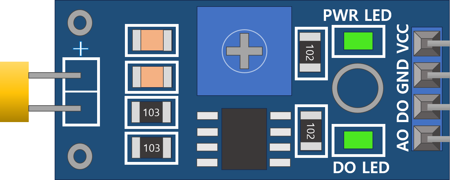
The CDS_Module by JJY is a light-dependent resistor (LDR) module designed to detect and respond to changes in ambient light intensity. The module's resistance decreases as the light intensity increases, making it an ideal choice for light-sensing applications. It is commonly used in projects such as automatic lighting systems, light-sensitive alarms, and brightness control systems.

Explore Projects Built with CDS_Module

Use Cirkit Designer to design, explore, and prototype these projects online. Some projects support real-time simulation. Click "Open Project" to start designing instantly!
DC-DC Converter and Relay Module Power Distribution System
Image of relay: A project utilizing CDS_Module in a practical application
This circuit consists of a DC-DC converter powering a 6-channel power module, which in turn supplies 5V to a 2-relay module. The power module distributes the converted voltage to the relay module, enabling it to control external devices.
Cirkit Designer LogoOpen Project in Cirkit Designer
Arduino 101 Based RFID and GSM Security System with I2C LCD Display and RTC
Image of id scanner with messaging system: A project utilizing CDS_Module in a practical application
This circuit features an Arduino 101 microcontroller interfaced with an RFID-RC522 module for RFID reading, a GSM SIM900 module for cellular communication, a DS3231 Real Time Clock for timekeeping, and an I2C LCD screen for display. The Arduino controls a buzzer connected to its D7 pin and communicates with the GSM module via serial connection on pins D0/RX and D1/TX. The RFID, RTC, and LCD modules are powered by the Arduino's 5V and 3.3V outputs, and they use I2C (SCL/SDA) for communication, except for the RFID module which uses SPI (MISO/MOSI/SCK) and a digital pin for reset (D9).
Cirkit Designer LogoOpen Project in Cirkit Designer
Cellular-Enabled IoT Device with Real-Time Clock and Power Management
Image of LRCM PHASE 2 BASIC: A project utilizing CDS_Module in a practical application
This circuit features a LilyGo-SIM7000G module for cellular communication and GPS functionality, interfaced with an RTC DS3231 for real-time clock capabilities. It includes voltage sensing through two voltage sensor modules, and uses an 8-channel opto-coupler for isolating different parts of the circuit. Power management is handled by a buck converter connected to a DC power source and batteries, with a fuse for protection and a rocker switch for on/off control. Additionally, there's an LED for indication purposes.
Cirkit Designer LogoOpen Project in Cirkit Designer
Arduino Mega 2560 Based Security System with Fingerprint Authentication and SMS Alerts
Image of Door security system: A project utilizing CDS_Module in a practical application
This circuit features an Arduino Mega 2560 microcontroller interfaced with a SIM800L GSM module, two fingerprint scanners, an I2C LCD display, an IR sensor, and a piezo buzzer. Power management is handled by a PowerBoost 1000 Basic Pad USB, a TP4056 charging module, and a Li-ion 18650 battery, with an option to use a Mini AC-DC 110V-230V to 5V 700mA module for direct power supply. The primary functionality appears to be a security system with GSM communication capabilities, biometric access control, and visual/audible feedback.
Cirkit Designer LogoOpen Project in Cirkit Designer

Explore Projects Built with CDS_Module

Use Cirkit Designer to design, explore, and prototype these projects online. Some projects support real-time simulation. Click "Open Project" to start designing instantly!
Image of relay: A project utilizing CDS_Module in a practical application
DC-DC Converter and Relay Module Power Distribution System
This circuit consists of a DC-DC converter powering a 6-channel power module, which in turn supplies 5V to a 2-relay module. The power module distributes the converted voltage to the relay module, enabling it to control external devices.
Cirkit Designer LogoOpen Project in Cirkit Designer
Image of id scanner with messaging system: A project utilizing CDS_Module in a practical application
Arduino 101 Based RFID and GSM Security System with I2C LCD Display and RTC
This circuit features an Arduino 101 microcontroller interfaced with an RFID-RC522 module for RFID reading, a GSM SIM900 module for cellular communication, a DS3231 Real Time Clock for timekeeping, and an I2C LCD screen for display. The Arduino controls a buzzer connected to its D7 pin and communicates with the GSM module via serial connection on pins D0/RX and D1/TX. The RFID, RTC, and LCD modules are powered by the Arduino's 5V and 3.3V outputs, and they use I2C (SCL/SDA) for communication, except for the RFID module which uses SPI (MISO/MOSI/SCK) and a digital pin for reset (D9).
Cirkit Designer LogoOpen Project in Cirkit Designer
Image of LRCM PHASE 2 BASIC: A project utilizing CDS_Module in a practical application
Cellular-Enabled IoT Device with Real-Time Clock and Power Management
This circuit features a LilyGo-SIM7000G module for cellular communication and GPS functionality, interfaced with an RTC DS3231 for real-time clock capabilities. It includes voltage sensing through two voltage sensor modules, and uses an 8-channel opto-coupler for isolating different parts of the circuit. Power management is handled by a buck converter connected to a DC power source and batteries, with a fuse for protection and a rocker switch for on/off control. Additionally, there's an LED for indication purposes.
Cirkit Designer LogoOpen Project in Cirkit Designer
Image of Door security system: A project utilizing CDS_Module in a practical application
Arduino Mega 2560 Based Security System with Fingerprint Authentication and SMS Alerts
This circuit features an Arduino Mega 2560 microcontroller interfaced with a SIM800L GSM module, two fingerprint scanners, an I2C LCD display, an IR sensor, and a piezo buzzer. Power management is handled by a PowerBoost 1000 Basic Pad USB, a TP4056 charging module, and a Li-ion 18650 battery, with an option to use a Mini AC-DC 110V-230V to 5V 700mA module for direct power supply. The primary functionality appears to be a security system with GSM communication capabilities, biometric access control, and visual/audible feedback.
Cirkit Designer LogoOpen Project in Cirkit Designer

Common Applications and Use Cases

  • Automatic streetlights
  • Light-sensitive alarms
  • Brightness adjustment systems
  • Solar tracking systems
  • DIY electronics projects involving light detection

Technical Specifications

The following table outlines the key technical details of the CDS_Module:

Parameter Value
Manufacturer JJY
Part ID CDS_Module
Operating Voltage 3.3V - 5V
Output Type Analog and Digital
Light Sensitivity Range 10 lux to 10,000 lux
Dimensions 32mm x 14mm x 8mm
Operating Temperature -20°C to 70°C

Pin Configuration and Descriptions

The CDS_Module has a 3-pin interface. The pinout is described in the table below:

Pin Name Description
1 VCC Power supply pin. Connect to 3.3V or 5V.
2 GND Ground pin. Connect to the ground of the circuit.
3 OUT Output pin. Provides an analog voltage proportional to light intensity or a
digital HIGH/LOW signal depending on the onboard potentiometer adjustment.

Usage Instructions

How to Use the Component in a Circuit

  1. Power the Module: Connect the VCC pin to a 3.3V or 5V power source and the GND pin to the ground.
  2. Connect the Output:
    • For analog light intensity readings, connect the OUT pin to an analog input pin of your microcontroller.
    • For digital light detection, adjust the onboard potentiometer to set the light threshold. The OUT pin will output HIGH (1) when the light intensity exceeds the threshold and LOW (0) otherwise.
  3. Calibrate the Module: Use the onboard potentiometer to fine-tune the light sensitivity threshold for your application.

Important Considerations and Best Practices

  • Power Supply: Ensure the module is powered within its operating voltage range (3.3V - 5V) to avoid damage.
  • Placement: Place the module in an area where it can receive unobstructed light for accurate readings.
  • Analog vs. Digital Output: Use the analog output for precise light intensity measurements and the digital output for simple light detection.
  • Potentiometer Adjustment: Turn the potentiometer clockwise to increase the light threshold and counterclockwise to decrease it.

Example: Connecting to an Arduino UNO

Below is an example of how to use the CDS_Module with an Arduino UNO to read light intensity:

// Define the pin connections
const int analogPin = A0; // Connect the OUT pin of the CDS_Module to A0
const int digitalPin = 2; // Optional: Connect OUT to digital pin 2 for threshold detection

void setup() {
  Serial.begin(9600); // Initialize serial communication for debugging
  pinMode(digitalPin, INPUT); // Set digital pin as input
}

void loop() {
  // Read the analog value from the CDS_Module
  int lightLevel = analogRead(analogPin);
  
  // Print the light intensity to the Serial Monitor
  Serial.print("Light Intensity (Analog): ");
  Serial.println(lightLevel);

  // Optional: Read the digital output
  int lightDetected = digitalRead(digitalPin);
  if (lightDetected == HIGH) {
    Serial.println("Light intensity is above the threshold.");
  } else {
    Serial.println("Light intensity is below the threshold.");
  }

  delay(500); // Wait for 500ms before the next reading
}

Troubleshooting and FAQs

Common Issues and Solutions

  1. No Output from the Module:

    • Ensure the module is powered correctly (3.3V or 5V).
    • Check all connections for loose wires or incorrect pin assignments.
  2. Inaccurate Light Readings:

    • Verify that the module is not obstructed by objects or shadows.
    • Adjust the potentiometer to calibrate the sensitivity.
  3. Digital Output Always HIGH or LOW:

    • Recalibrate the potentiometer to set an appropriate light threshold.
    • Ensure the light intensity in the environment is within the module's sensitivity range.
  4. Analog Readings Are Unstable:

    • Use a capacitor (e.g., 0.1µF) between the OUT pin and ground to filter noise.
    • Avoid placing the module near sources of electrical interference.

FAQs

Q1: Can the CDS_Module detect light color?
No, the CDS_Module is designed to detect light intensity, not color.

Q2: Can I use the module with a 3.3V microcontroller like ESP32?
Yes, the module is compatible with both 3.3V and 5V systems.

Q3: How do I know if the potentiometer is set correctly?
You can monitor the digital output pin. Adjust the potentiometer until the output changes state at the desired light level.

Q4: What is the maximum distance for light detection?
The detection range depends on the light source's intensity. For typical indoor lighting, the module can detect light from several meters away.

Q5: Can I use multiple CDS_Modules in the same circuit?
Yes, you can use multiple modules. Ensure each module's output is connected to a separate input pin on your microcontroller.