How to Use mks dlc32 v2.1: Examples, Pinouts, and Specs
Introduction
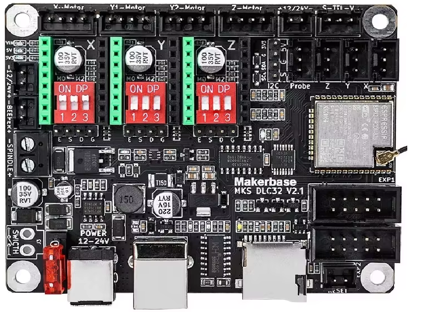
The MakerBase MKS DLC32 V2.1 is a 3-axis motion control system designed for applications requiring precise movement along the X, Y, and Z axes. This system is widely used in CNC machines, 3D printers, laser engravers, and other robotics applications. It integrates advanced motion control capabilities with a user-friendly interface, making it suitable for both hobbyists and professionals.
The MKS DLC32 V2.1 is based on the ESP32 microcontroller, offering wireless connectivity (Wi-Fi and Bluetooth) for remote control and monitoring. Its compact design and compatibility with GRBL firmware make it a versatile choice for motion control projects.
Explore Projects Built with mks dlc32 v2.1

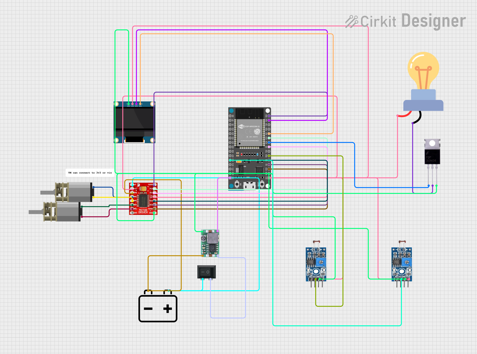
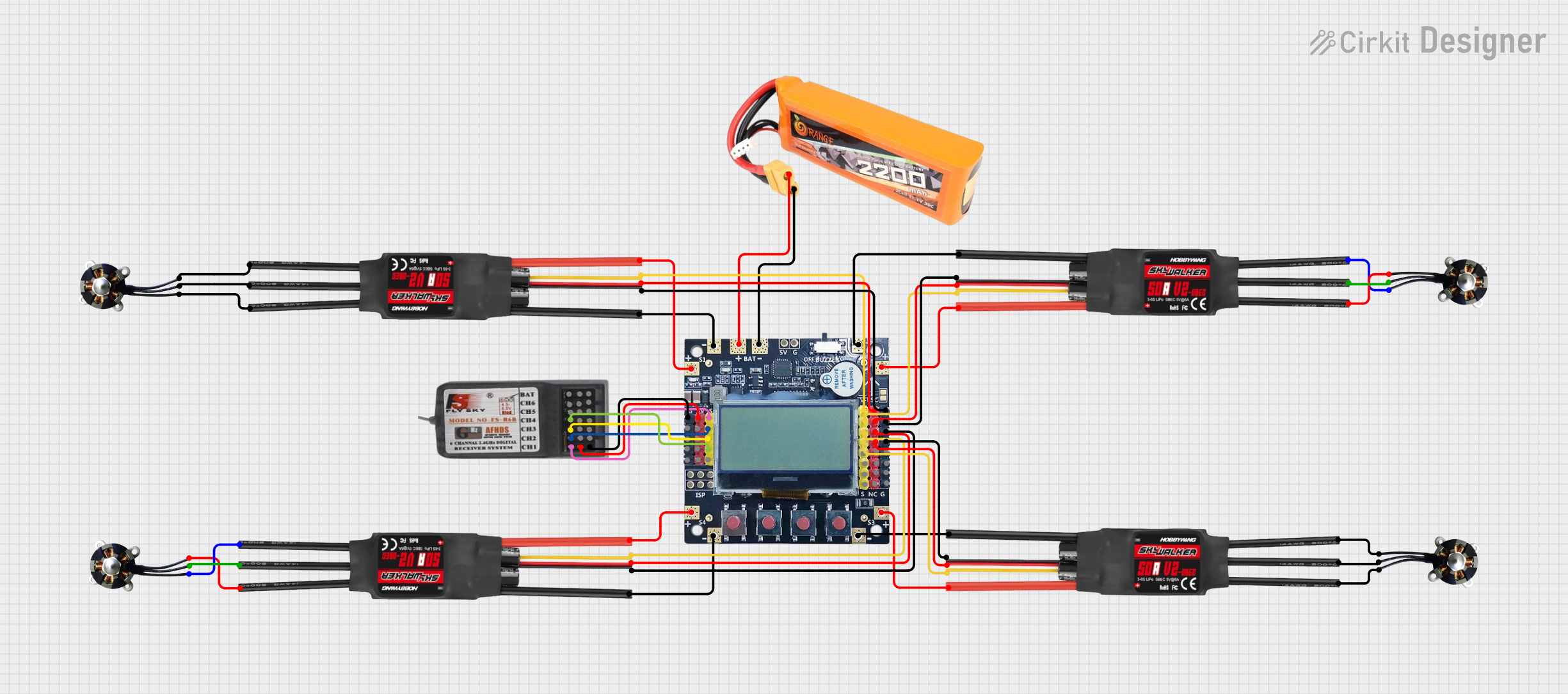
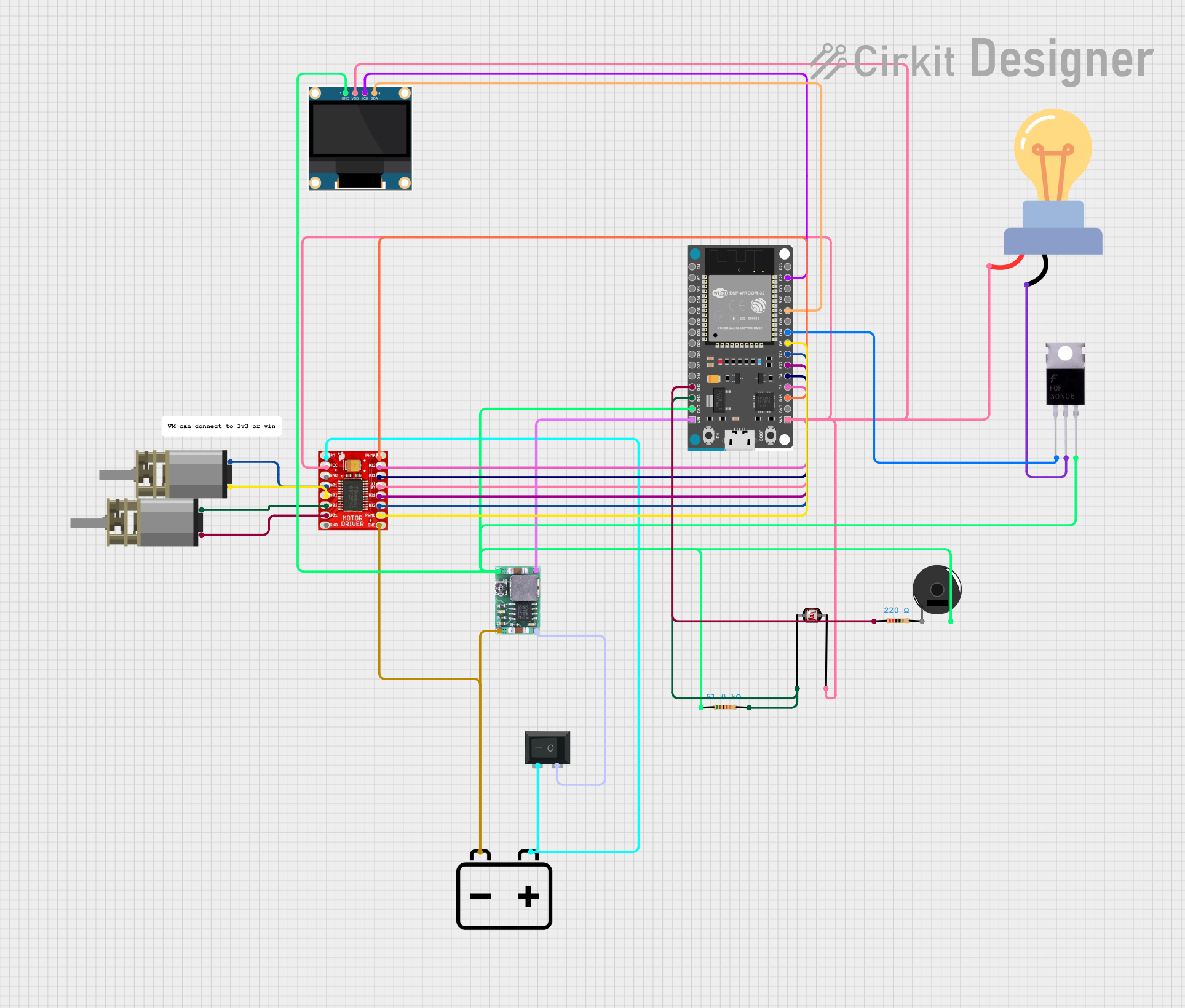
Explore Projects Built with mks dlc32 v2.1
Common Applications
- CNC milling machines
- 3D printers
- Laser engraving and cutting machines
- Robotics and automation systems
- Educational and DIY projects
Technical Specifications
Key Technical Details
| Parameter | Specification |
|---|---|
| Microcontroller | ESP32 |
| Input Voltage | 12V - 24V DC |
| Stepper Motor Drivers | Supports external stepper drivers (e.g., TMC2209, A4988) |
| Axis Support | X, Y, Z |
| Connectivity | Wi-Fi, Bluetooth |
| Firmware Compatibility | GRBL 1.1 |
| Dimensions | 100mm x 70mm |
| Operating Temperature | 0°C to 50°C |
Pin Configuration and Descriptions
The MKS DLC32 V2.1 features multiple connectors for stepper motors, limit switches, and other peripherals. Below is the pin configuration:
Stepper Motor Connections
| Pin Label | Description |
|---|---|
| X+ | Stepper motor connection for X-axis (positive direction) |
| X- | Stepper motor connection for X-axis (negative direction) |
| Y+ | Stepper motor connection for Y-axis (positive direction) |
| Y- | Stepper motor connection for Y-axis (negative direction) |
| Z+ | Stepper motor connection for Z-axis (positive direction) |
| Z- | Stepper motor connection for Z-axis (negative direction) |
Limit Switch Connections
| Pin Label | Description |
|---|---|
| X Limit | Limit switch for X-axis |
| Y Limit | Limit switch for Y-axis |
| Z Limit | Limit switch for Z-axis |
Power and Communication
| Pin Label | Description |
|---|---|
| VIN | Power input (12V - 24V DC) |
| GND | Ground |
| TX | UART transmit pin |
| RX | UART receive pin |
Usage Instructions
How to Use the Component in a Circuit
- Power Supply: Connect a 12V-24V DC power supply to the VIN and GND terminals.
- Stepper Motors: Attach stepper motors to the X, Y, and Z motor connectors. Ensure the wiring matches the motor driver specifications.
- Limit Switches: Connect limit switches to the X, Y, and Z limit pins for homing and safety.
- Firmware: Flash the GRBL 1.1 firmware onto the ESP32 microcontroller using a USB connection.
- Control Software: Use compatible software like LaserGRBL or Universal Gcode Sender to send G-code commands to the system.
- Wireless Connectivity: Configure Wi-Fi or Bluetooth settings for remote control via a web interface or mobile app.
Important Considerations and Best Practices
- Power Supply: Ensure the power supply voltage matches the requirements of the stepper motors and the MKS DLC32 V2.1 board.
- Cooling: Use heatsinks or fans for stepper motor drivers to prevent overheating during extended operation.
- Firmware Updates: Regularly update the GRBL firmware to access new features and bug fixes.
- Cable Management: Organize cables to avoid interference and ensure smooth operation of the motion system.
- Safety: Always use limit switches to prevent the system from exceeding its physical limits.
Example Code for Arduino UNO
If you are using the MKS DLC32 V2.1 with an Arduino UNO for additional control, you can use the following example code to send basic G-code commands:
#include <SoftwareSerial.h>

// Define RX and TX pins for communication with the MKS DLC32
SoftwareSerial mySerial(10, 11); // RX, TX

void setup() {
  // Initialize serial communication
  Serial.begin(9600); // Communication with PC
  mySerial.begin(115200); // Communication with MKS DLC32

  // Send initialization commands
  mySerial.println("$X"); // Unlock the GRBL system
  delay(1000);
  mySerial.println("G21"); // Set units to millimeters
  delay(1000);
  mySerial.println("G90"); // Set to absolute positioning
}

void loop() {
  // Example: Move to X=10, Y=10, Z=5
  mySerial.println("G1 X10 Y10 Z5 F1000"); // Linear move with feed rate
  delay(5000); // Wait for the move to complete
}
Troubleshooting and FAQs
Common Issues and Solutions
Stepper Motors Not Moving
- Cause: Incorrect wiring or insufficient power supply.
- Solution: Double-check motor connections and ensure the power supply meets the voltage and current requirements.
Wi-Fi Connection Fails
- Cause: Incorrect Wi-Fi credentials or firmware issue.
- Solution: Reconfigure Wi-Fi settings and ensure the firmware is up to date.
Overheating Drivers
- Cause: Prolonged operation without proper cooling.
- Solution: Install heatsinks or cooling fans on the stepper motor drivers.
Limit Switches Not Working
- Cause: Faulty wiring or incorrect configuration.
- Solution: Verify the limit switch connections and check the GRBL configuration settings.
FAQs
Q: Can I use this system with NEMA 17 stepper motors?
A: Yes, the MKS DLC32 V2.1 is compatible with NEMA 17 stepper motors. Ensure the motor drivers are configured correctly.
Q: Is the firmware pre-installed?
A: The board typically comes with GRBL firmware pre-installed, but you can reflash it if needed.
Q: Can I control the system via Bluetooth?
A: Yes, the ESP32 microcontroller supports Bluetooth communication for remote control.
Q: What software is recommended for G-code generation?
A: Popular options include LaserGRBL, Universal Gcode Sender, and Fusion 360 for CAD/CAM workflows.
This documentation provides a comprehensive guide to the MakerBase MKS DLC32 V2.1 3-axis motion system, ensuring users can set up and operate the component effectively.