
How to Use Adafruit H3LIS331 Triple-Axis Accelerometer: Examples, Pinouts, and Specs
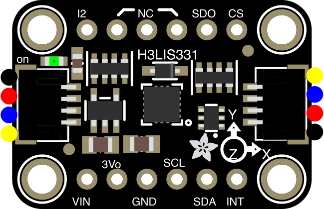
 Design with Adafruit H3LIS331 Triple-Axis Accelerometer in Cirkit Designer
Introduction
The Adafruit H3LIS331 Triple-Axis Accelerometer (Manufacturer Part ID: 4627) is a compact and high-performance sensor designed to measure acceleration in three axes: X, Y, and Z. It is capable of detecting motion, orientation, and vibration, making it ideal for a wide range of applications. With its robust design and configurable sensitivity, the H3LIS331 is suitable for industrial, automotive, and consumer electronics projects.
Explore Projects Built with Adafruit H3LIS331 Triple-Axis Accelerometer
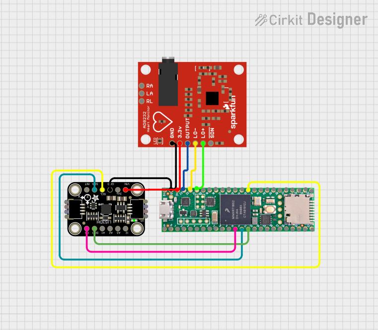 Open Project in Cirkit Designer
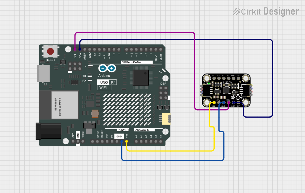 Open Project in Cirkit Designer
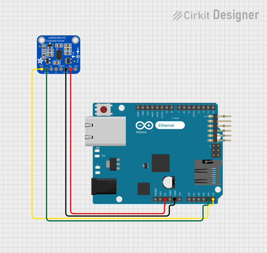 Open Project in Cirkit Designer
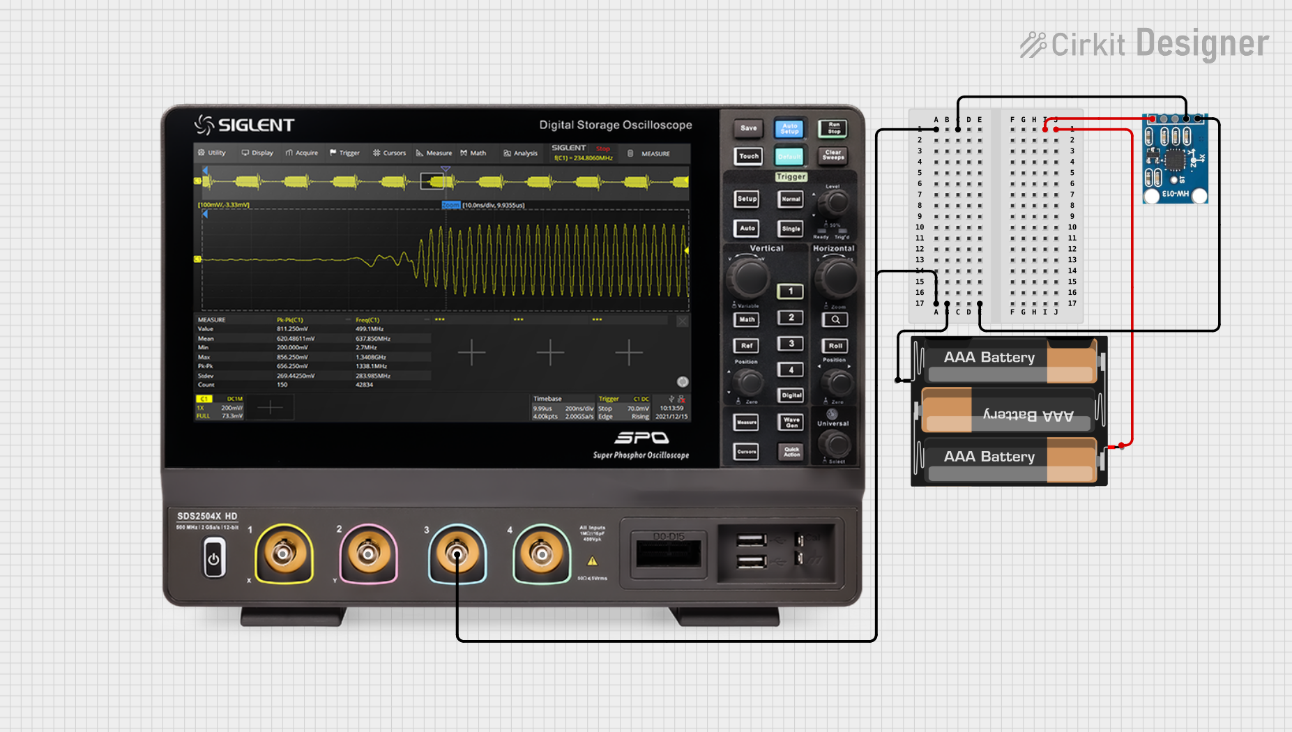 Open Project in Cirkit Designer
Explore Projects Built with Adafruit H3LIS331 Triple-Axis Accelerometer
Open Project in Cirkit DesignerOpen Project in Cirkit DesignerOpen Project in Cirkit DesignerOpen Project in Cirkit DesignerCommon Applications
- Motion detection and vibration monitoring
- Orientation sensing in robotics and drones
- Impact detection in industrial equipment
- Wearable devices and fitness trackers
- Gaming and virtual reality controllers
Technical Specifications
The following table outlines the key technical details of the Adafruit H3LIS331 Triple-Axis Accelerometer:
| Parameter | Value |
|---|---|
| Operating Voltage | 2.16V to 3.6V |
| Communication Interface | I²C (up to 400 kHz) and SPI (up to 10 MHz) |
| Measurement Range | ±100g, ±200g, ±400g (configurable) |
| Output Data Rate (ODR) | 0.5 Hz to 1 kHz |
| Operating Temperature | -40°C to +85°C |
| Power Consumption | 10 µA (low-power mode) |
| Dimensions | 20mm x 20mm x 3mm |
Pin Configuration and Descriptions
The H3LIS331 breakout board includes the following pins:
| Pin | Name | Description |
|---|---|---|
| 1 | VIN | Power input (2.16V to 3.6V). Connect to the 3.3V or 5V supply of your microcontroller. |
| 2 | GND | Ground connection. |
| 3 | SDA | I²C data line. Connect to the SDA pin of your microcontroller. |
| 4 | SCL | I²C clock line. Connect to the SCL pin of your microcontroller. |
| 5 | CS | Chip Select for SPI communication. Pull low to enable SPI. |
| 6 | SDO/SA0 | SPI data output or I²C address selection. |
| 7 | INT1 | Interrupt 1 output. Configurable for motion detection or other events. |
| 8 | INT2 | Interrupt 2 output. Configurable for motion detection or other events. |
Usage Instructions
How to Use the Component in a Circuit
- Power the Sensor: Connect the VIN pin to a 3.3V or 5V power source and the GND pin to ground.
- Choose Communication Protocol:
- For I²C: Connect the SDA and SCL pins to the corresponding pins on your microcontroller.
- For SPI: Connect the CS, SDO/SA0, and SPI clock/data pins to your microcontroller.
- Configure the Sensor: Use the Adafruit H3LIS331 library to set the measurement range, output data rate, and interrupt settings.
- Read Data: Use the library functions to read acceleration values for the X, Y, and Z axes.
Important Considerations and Best Practices
- Voltage Compatibility: Ensure your microcontroller's logic level matches the sensor's operating voltage (3.3V or 5V).
- Pull-Up Resistors: If using I²C, ensure pull-up resistors (typically 4.7kΩ) are present on the SDA and SCL lines.
- Mounting Orientation: Secure the sensor firmly to avoid inaccurate readings due to vibrations or loose connections.
- Interrupt Configuration: Use the INT1 and INT2 pins for advanced features like motion detection or free-fall detection.
Example Code for Arduino UNO
Below is an example of how to use the H3LIS331 with an Arduino UNO via I²C:
#include <Wire.h>
#include <Adafruit_H3LIS331.h>

// Create an instance of the H3LIS331 class
Adafruit_H3LIS331 h3lis = Adafruit_H3LIS331();

void setup() {
  Serial.begin(9600);
  while (!Serial) {
    delay(10); // Wait for Serial Monitor to open
  }

  // Initialize the sensor
  if (!h3lis.begin()) {
    Serial.println("Failed to find H3LIS331 sensor!");
    while (1) {
      delay(10); // Halt if sensor initialization fails
    }
  }
  Serial.println("H3LIS331 sensor initialized!");

  // Set measurement range to ±200g
  h3lis.setRange(H3LIS331_RANGE_200_G);

  // Set output data rate to 50 Hz
  h3lis.setDataRate(H3LIS331_DATARATE_50_HZ);
}

void loop() {
  // Read acceleration values
  sensors_event_t event;
  h3lis.getEvent(&event);

  // Print acceleration values to Serial Monitor
  Serial.print("X: ");
  Serial.print(event.acceleration.x);
  Serial.print(" m/s^2, Y: ");
  Serial.print(event.acceleration.y);
  Serial.print(" m/s^2, Z: ");
  Serial.print(event.acceleration.z);
  Serial.println(" m/s^2");

  delay(100); // Delay for readability
}
Troubleshooting and FAQs
Common Issues
Sensor Not Detected:
- Ensure the VIN and GND pins are properly connected.
- Verify the I²C address (default: 0x18 or 0x19 depending on SA0 pin state).
- Check for loose or incorrect wiring.
Incorrect or No Data:
- Confirm the measurement range and data rate settings are appropriate for your application.
- Ensure the sensor is mounted securely to avoid vibrations affecting readings.
Interrupts Not Triggering:
- Verify the interrupt configuration in your code.
- Check the INT1 and INT2 pin connections.
Tips for Troubleshooting
- Use a multimeter to verify power and ground connections.
- Test the I²C or SPI communication using a logic analyzer if available.
- Refer to the Adafruit H3LIS331 library documentation for advanced configuration options.
By following this documentation, you can effectively integrate the Adafruit H3LIS331 Triple-Axis Accelerometer into your projects for reliable motion and orientation sensing.