Cirkit Designer Logo
Cirkit Designer
Your all-in-one circuit design IDE
Home / 
Component Documentation

How to Use biscute emg sensor: Examples, Pinouts, and Specs

Image of biscute emg  sensor
Cirkit Designer LogoDesign with biscute emg sensor in Cirkit Designer

Introduction

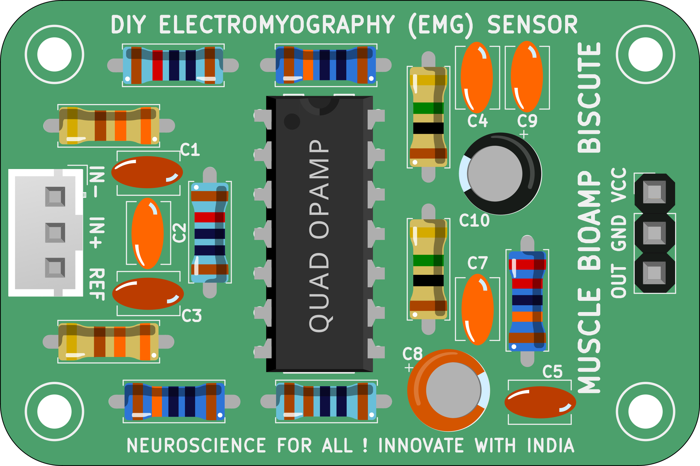
The Biscute EMG Sensor, manufactured by Upside Down Labs (Part ID: EMG Sensor Biscute DIY Kit), is a compact and efficient device designed to measure the electrical activity generated by skeletal muscles. This sensor captures electromyographic (EMG) signals, which are essential for applications in prosthetics control, rehabilitation, human-computer interaction, and biofeedback systems. Its small form factor and ease of use make it ideal for DIY projects, research, and educational purposes.

Explore Projects Built with biscute emg sensor

Use Cirkit Designer to design, explore, and prototype these projects online. Some projects support real-time simulation. Click "Open Project" to start designing instantly!
ESP32 and ESP8266 Wi-Fi Controlled Sensor Hub with Battery Backup
Image of baby guard: A project utilizing biscute emg  sensor in a practical application
This circuit is a sensor monitoring and data transmission system powered by a Li-ion battery and a 12V adapter. It includes various sensors (tilt, optical encoder, force sensing resistors, and air pressure) connected to an ESP32 microcontroller, which reads sensor data and transmits it via a WiFi module (ESP8266-01). The system is designed to provide real-time sensor data over a WiFi network.
Cirkit Designer LogoOpen Project in Cirkit Designer
ESP32-Based Wi-Fi Controlled Robotic System with Multiple Sensors and Motor Drivers
Image of mit: A project utilizing biscute emg  sensor in a practical application
This circuit is a sensor and motor control system powered by a 9V battery and regulated by a buck converter. It includes multiple sensors (SEN0245, SEN0427, I2C BMI160) connected via I2C to an ESP32 microcontroller, which also controls two N20 motors with encoders through an MX1508 DC motor driver.
Cirkit Designer LogoOpen Project in Cirkit Designer
Arduino-Powered EMG Sensor-Controlled Dual Servo System
Image of ARDUINO LIKHA EXOSKELETON: A project utilizing biscute emg  sensor in a practical application
This circuit uses an Arduino UNO to control two servos based on input from an EMG sensor. The EMG sensor is powered by two 9V batteries and sends its signal to the Arduino, which then drives the servos connected to its digital pins.
Cirkit Designer LogoOpen Project in Cirkit Designer
Arduino-Controlled Servo with EMG Sensor Activation
Image of ARDUINO LIKHA EXOSKELETON: A project utilizing biscute emg  sensor in a practical application
This circuit is designed to control a servo motor based on the signal from an EMG sensor, with the Arduino UNO as the central processing unit. The EMG sensor detects muscle activity, and when the signal exceeds a certain threshold, the servo motor is activated to move to a specific position. The pushbutton is connected to the Arduino to ground, likely for a reset or mode selection function, and the two 9V batteries power the EMG sensor and possibly the Arduino and servo.
Cirkit Designer LogoOpen Project in Cirkit Designer

Explore Projects Built with biscute emg sensor

Use Cirkit Designer to design, explore, and prototype these projects online. Some projects support real-time simulation. Click "Open Project" to start designing instantly!
Image of baby guard: A project utilizing biscute emg  sensor in a practical application
ESP32 and ESP8266 Wi-Fi Controlled Sensor Hub with Battery Backup
This circuit is a sensor monitoring and data transmission system powered by a Li-ion battery and a 12V adapter. It includes various sensors (tilt, optical encoder, force sensing resistors, and air pressure) connected to an ESP32 microcontroller, which reads sensor data and transmits it via a WiFi module (ESP8266-01). The system is designed to provide real-time sensor data over a WiFi network.
Cirkit Designer LogoOpen Project in Cirkit Designer
Image of mit: A project utilizing biscute emg  sensor in a practical application
ESP32-Based Wi-Fi Controlled Robotic System with Multiple Sensors and Motor Drivers
This circuit is a sensor and motor control system powered by a 9V battery and regulated by a buck converter. It includes multiple sensors (SEN0245, SEN0427, I2C BMI160) connected via I2C to an ESP32 microcontroller, which also controls two N20 motors with encoders through an MX1508 DC motor driver.
Cirkit Designer LogoOpen Project in Cirkit Designer
Image of ARDUINO LIKHA EXOSKELETON: A project utilizing biscute emg  sensor in a practical application
Arduino-Powered EMG Sensor-Controlled Dual Servo System
This circuit uses an Arduino UNO to control two servos based on input from an EMG sensor. The EMG sensor is powered by two 9V batteries and sends its signal to the Arduino, which then drives the servos connected to its digital pins.
Cirkit Designer LogoOpen Project in Cirkit Designer
Image of ARDUINO LIKHA EXOSKELETON: A project utilizing biscute emg  sensor in a practical application
Arduino-Controlled Servo with EMG Sensor Activation
This circuit is designed to control a servo motor based on the signal from an EMG sensor, with the Arduino UNO as the central processing unit. The EMG sensor detects muscle activity, and when the signal exceeds a certain threshold, the servo motor is activated to move to a specific position. The pushbutton is connected to the Arduino to ground, likely for a reset or mode selection function, and the two 9V batteries power the EMG sensor and possibly the Arduino and servo.
Cirkit Designer LogoOpen Project in Cirkit Designer

Common Applications

  • Prosthetics and robotic limb control
  • Rehabilitation and physiotherapy monitoring
  • Gesture-based human-computer interaction
  • Wearable technology and biofeedback systems
  • Research and development in biomedical engineering

Technical Specifications

The Biscute EMG Sensor is designed to provide reliable and accurate EMG signal acquisition. Below are its key technical details:

Parameter Specification
Operating Voltage 3.3V to 5V DC
Operating Current < 10mA
Output Signal Analog (0V to 3.3V)
Gain Adjustable (default: 1000x)
Frequency Response 20Hz to 500Hz
Input Impedance > 10MΩ
Electrode Type Snap-on or adhesive gel electrodes
Dimensions 35mm x 25mm x 5mm

Pin Configuration

The Biscute EMG Sensor has a simple pinout for easy integration into circuits:

Pin Name Description
1 VCC Power supply input (3.3V to 5V DC)
2 GND Ground connection
3 SIG Analog output signal representing EMG activity

Usage Instructions

How to Use the Biscute EMG Sensor in a Circuit

  1. Power the Sensor: Connect the VCC pin to a 3.3V or 5V DC power source and the GND pin to the ground of your circuit.
  2. Connect Electrodes: Attach the snap-on or adhesive gel electrodes to the sensor. Place the electrodes on the target muscle group as follows:
    • Two electrodes on the muscle (active electrodes).
    • One electrode on a bony or non-muscular area (reference electrode).
  3. Read the Signal: Connect the SIG pin to an analog input pin of a microcontroller (e.g., Arduino UNO) or an oscilloscope to monitor the EMG signal.
  4. Adjust Gain (if needed): Use the onboard potentiometer to adjust the gain for optimal signal amplification.

Important Considerations

  • Ensure proper skin preparation (clean and dry) before attaching electrodes to reduce noise.
  • Use high-quality electrodes for better signal acquisition.
  • Avoid placing the sensor near sources of electromagnetic interference (e.g., motors, power supplies).
  • Keep the electrode cables as short as possible to minimize noise.

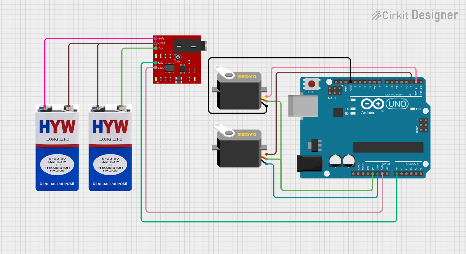
Example: Connecting to an Arduino UNO

Below is an example of how to connect and read data from the Biscute EMG Sensor using an Arduino UNO:

Circuit Connections

  • VCC → 5V pin on Arduino
  • GND → GND pin on Arduino
  • SIG → A0 (Analog Pin 0) on Arduino

Arduino Code

// Biscute EMG Sensor Example Code
// This code reads the analog signal from the EMG sensor and prints it to the Serial Monitor.

const int emgPin = A0; // Analog pin connected to the SIG pin of the sensor

void setup() {
  Serial.begin(9600); // Initialize serial communication at 9600 baud
  pinMode(emgPin, INPUT); // Set the EMG pin as input
}

void loop() {
  int emgValue = analogRead(emgPin); // Read the analog value from the sensor
  Serial.println(emgValue); // Print the value to the Serial Monitor
  delay(10); // Small delay for stable readings
}

Notes:

  • Open the Serial Monitor in the Arduino IDE to view the EMG signal values.
  • You can process the signal further for applications like gesture recognition or muscle activity monitoring.

Troubleshooting and FAQs

Common Issues and Solutions

  1. No Signal or Weak Signal

    • Ensure the electrodes are properly attached to the skin.
    • Check the power supply and connections.
    • Verify that the gain is set appropriately.
  2. Noisy or Erratic Signal

    • Ensure the skin is clean and dry before attaching electrodes.
    • Use shielded cables to reduce electromagnetic interference.
    • Keep the sensor away from high-frequency noise sources.
  3. Signal Saturation

    • Reduce the gain using the onboard potentiometer.
    • Ensure the electrodes are not placed too close to each other.

FAQs

Q: Can I use the Biscute EMG Sensor with a 3.3V microcontroller?
A: Yes, the sensor operates at both 3.3V and 5V, making it compatible with 3.3V microcontrollers like the ESP32.

Q: What type of electrodes should I use?
A: Snap-on or adhesive gel electrodes are recommended for optimal performance.

Q: Can I use this sensor for real-time prosthetics control?
A: Yes, the Biscute EMG Sensor is suitable for real-time applications like prosthetics control, provided the signal is processed appropriately.

Q: How do I clean the electrodes?
A: For reusable electrodes, clean them with a damp cloth and mild soap. Do not immerse the sensor in water.

By following this documentation, you can effectively integrate and utilize the Biscute EMG Sensor in your projects.