How to Use Ardupilot Mega APM 2.8: Examples, Pinouts, and Specs
Introduction
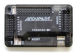
The Ardupilot Mega APM 2.8, manufactured by ATMEGA2560 (Part ID: APM), is an open-source flight control hardware platform designed for drones and other unmanned vehicles. It is equipped with a powerful 32-bit processor and supports multiple sensor inputs, enabling precise control and navigation. The APM 2.8 is widely used in aerial robotics for its versatility, reliability, and compatibility with various flight modes.
Explore Projects Built with Ardupilot Mega APM 2.8

Explore Projects Built with Ardupilot Mega APM 2.8
Common Applications and Use Cases
- Multirotor drones (quadcopters, hexacopters, etc.)
- Fixed-wing aircraft
- Autonomous ground vehicles (rovers)
- Marine vehicles (boats, submarines)
- Research and development in robotics and UAVs
- Hobbyist drone projects and professional aerial photography
Technical Specifications
The following table outlines the key technical details of the Ardupilot Mega APM 2.8:
| Specification | Details |
|---|---|
| Processor | ATMEGA2560 8-bit microcontroller |
| Input Voltage | 5V DC (via USB) or 7V–12V DC (via power module or external power source) |
| Supported Sensors | Gyroscope, accelerometer, magnetometer, barometer |
| Communication Interfaces | UART, I2C, SPI, PWM, ADC |
| Flash Memory | 256 KB |
| RAM | 8 KB |
| EEPROM | 4 KB |
| Dimensions | 70 mm x 45 mm |
| Weight | 28 grams |
| Operating Temperature | -40°C to 85°C |
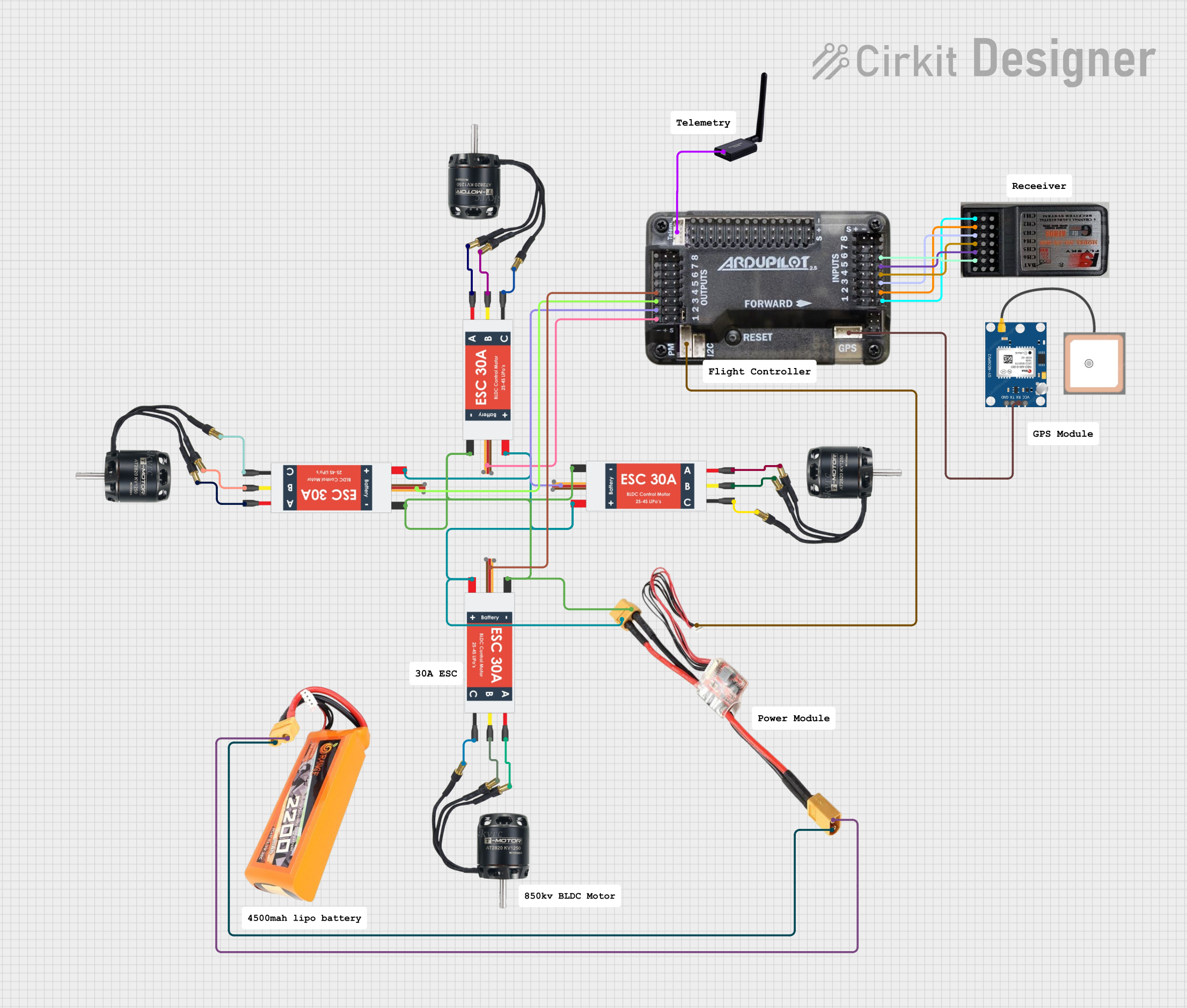
Pin Configuration and Descriptions
The APM 2.8 features multiple input/output pins for connecting sensors, motors, and other peripherals. Below is the pin configuration:
Power and Communication Pins
| Pin | Description |
|---|---|
| USB Port | Used for programming and powering the board during setup. |
| Power Module | Provides power to the board and measures battery voltage/current. |
| UART Ports | Serial communication ports for telemetry modules or external devices. |
| I2C Port | Interface for connecting external sensors like magnetometers or barometers. |
Motor and Servo Outputs
| Pin | Description |
|---|---|
| PWM Outputs | 8 PWM channels for controlling motors or servos. |
| AUX Outputs | Additional PWM outputs for auxiliary functions. |
Sensor Inputs
| Pin | Description |
|---|---|
| Analog Inputs | 6 analog input pins for connecting external sensors. |
| GPS Port | Dedicated port for GPS module connection. |
Usage Instructions
How to Use the APM 2.8 in a Circuit
Powering the Board:
- Connect the power module to the APM 2.8's power input port. Ensure the input voltage is within the range of 7V–12V.
- Alternatively, you can power the board via USB during setup or testing.
Connecting Peripherals:
- Attach the GPS module to the dedicated GPS port.
- Connect the telemetry module to the UART port for real-time data transmission.
- Plug in ESCs (Electronic Speed Controllers) or servos to the PWM output pins.
Programming the Board:
- Install the Mission Planner software on your computer.
- Connect the APM 2.8 to your computer via USB.
- Use Mission Planner to upload the desired firmware (e.g., ArduCopter, ArduPlane).
Calibrating Sensors:
- Use Mission Planner to calibrate the accelerometer, gyroscope, compass, and radio.
- Follow the on-screen instructions for each calibration step.
Flight Testing:
- Ensure all connections are secure and the battery is fully charged.
- Perform a pre-flight check using Mission Planner.
- Test the drone in a safe, open area.
Important Considerations and Best Practices
- Power Supply: Always use a stable power source to avoid voltage fluctuations that may cause the board to reset mid-flight.
- Firmware Updates: Regularly update the firmware to access new features and bug fixes.
- Vibration Isolation: Mount the APM 2.8 on vibration-dampening material to improve sensor accuracy.
- Failsafe Configuration: Configure failsafe settings in Mission Planner to ensure safe operation in case of signal loss or low battery.
Example Code for Arduino UNO Integration
The APM 2.8 can communicate with an Arduino UNO via UART. Below is an example code snippet for reading telemetry data:
#include <SoftwareSerial.h>

// Define RX and TX pins for communication with APM 2.8
SoftwareSerial apmSerial(10, 11); // RX = pin 10, TX = pin 11

void setup() {
  Serial.begin(9600); // Initialize serial monitor
  apmSerial.begin(57600); // Initialize APM communication at 57600 baud rate

  Serial.println("APM 2.8 Telemetry Communication Initialized");
}

void loop() {
  // Check if data is available from APM
  if (apmSerial.available()) {
    String telemetryData = "";

    // Read data from APM
    while (apmSerial.available()) {
      telemetryData += (char)apmSerial.read();
    }

    // Print telemetry data to serial monitor
    Serial.println("Telemetry Data: " + telemetryData);
  }

  delay(100); // Small delay to avoid flooding the serial monitor
}
Troubleshooting and FAQs
Common Issues and Solutions
Board Not Detected by Mission Planner:
- Ensure the USB cable is properly connected.
- Check if the correct COM port is selected in Mission Planner.
- Install the necessary USB drivers for the APM 2.8.
Unstable Flight or Drifting:
- Recalibrate the accelerometer, gyroscope, and compass.
- Check for loose connections or excessive vibrations.
No GPS Lock:
- Ensure the GPS module is connected to the correct port.
- Test the GPS module outdoors with a clear view of the sky.
Telemetry Module Not Working:
- Verify the baud rate settings in Mission Planner match the telemetry module.
- Check the wiring and ensure the module is powered.
FAQs
Can the APM 2.8 be used with fixed-wing aircraft?
Yes, the APM 2.8 supports ArduPlane firmware for fixed-wing aircraft.What is the maximum number of motors supported?
The APM 2.8 supports up to 8 motors via PWM outputs.Is the APM 2.8 compatible with LiPo batteries?
Yes, it is compatible with 2S–6S LiPo batteries when used with a power module.Can I use the APM 2.8 without a GPS module?
Yes, but certain features like autonomous navigation and return-to-home will not be available.