How to Use BMS 6S 100A: Examples, Pinouts, and Specs
Introduction
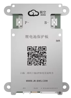
The BMS 6S 100A by Jikong is a Battery Management System designed for managing and protecting lithium-ion battery packs with six series-connected cells (6S configuration). It ensures safe operation by monitoring individual cell voltages, pack temperature, and current flow. The BMS also provides cell balancing during charging and discharging, which helps to extend the overall lifespan of the battery pack.
Explore Projects Built with BMS 6S 100A


Explore Projects Built with BMS 6S 100A
Common Applications
- Electric vehicles (e-bikes, scooters, and cars)
- Solar energy storage systems
- Uninterruptible Power Supplies (UPS)
- Power tools and industrial equipment
- DIY battery pack projects
Technical Specifications
The following table outlines the key technical details of the BMS 6S 100A:
| Parameter | Value |
|---|---|
| Battery Configuration | 6 series-connected lithium-ion cells (6S) |
| Maximum Continuous Current | 100A |
| Overcharge Protection | 4.2V ± 0.05V per cell |
| Overdischarge Protection | 2.8V ± 0.05V per cell |
| Balancing Current | 60mA |
| Operating Temperature | -20°C to 60°C |
| Dimensions | 120mm x 60mm x 10mm |
| Weight | ~150g |
Pin Configuration and Descriptions
The BMS 6S 100A has multiple connection points for the battery pack, load, and charger. Below is the pin configuration:
| Pin Name | Description |
|---|---|
| B- | Battery pack negative terminal |
| B1, B2, B3, B4, B5, B6 | Connections to the positive terminals of each cell in the 6S configuration |
| P- | Load negative terminal |
| C- | Charger negative terminal |
| P+ | Common positive terminal for both load and charger |
Usage Instructions
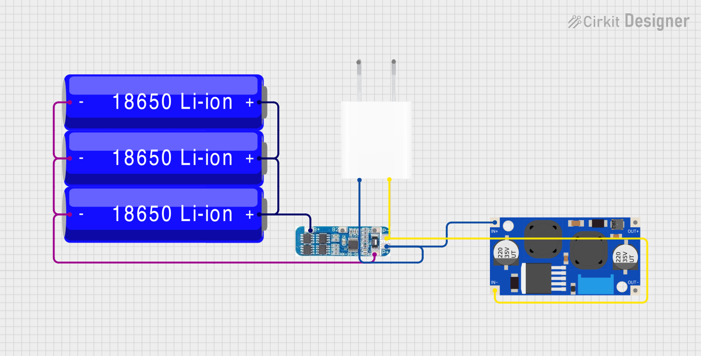
How to Use the BMS in a Circuit
Wiring the Battery Pack:
- Connect the B- terminal to the negative terminal of the battery pack.
- Connect the positive terminals of each cell to the corresponding pins (B1 to B6) in sequence.
- Ensure all connections are secure and insulated to prevent short circuits.
Connecting the Load and Charger:
- Connect the load's negative terminal to the P- pin.
- Connect the charger's negative terminal to the C- pin.
- The P+ terminal serves as the common positive terminal for both the load and charger.
Powering On:
- Once all connections are made, the BMS will automatically monitor and manage the battery pack.
- During charging, the BMS will balance the cells to ensure uniform voltage levels.
Important Considerations and Best Practices
- Cell Matching: Use cells with similar capacities and internal resistances to ensure optimal performance.
- Heat Dissipation: Ensure proper ventilation or heat sinking for the BMS, especially when operating at high currents.
- Avoid Overloading: Do not exceed the maximum continuous current rating of 100A.
- Check Connections: Double-check all wiring before powering on to avoid damage to the BMS or battery pack.
- Firmware Updates: If applicable, check for firmware updates from the manufacturer to improve performance.
Arduino UNO Integration Example
The BMS itself does not directly interface with an Arduino, but you can monitor the battery pack's voltage using an Arduino and a voltage divider circuit. Below is an example code snippet for reading the voltage of a single cell:
// Arduino code to read the voltage of a single cell in a 6S battery pack
// Ensure the voltage divider reduces the cell voltage to below 5V for safe ADC input

const int voltagePin = A0; // Analog pin connected to the voltage divider
float voltageDividerRatio = 5.0; // Adjust based on your resistor values

void setup() {
  Serial.begin(9600); // Initialize serial communication
}

void loop() {
  int rawADC = analogRead(voltagePin); // Read the analog value
  float cellVoltage = (rawADC * 5.0 / 1023.0) * voltageDividerRatio;

  // Print the cell voltage to the Serial Monitor
  Serial.print("Cell Voltage: ");
  Serial.print(cellVoltage);
  Serial.println(" V");

  delay(1000); // Wait for 1 second before the next reading
}
Note: Use appropriate resistor values in the voltage divider to ensure the input voltage to the Arduino does not exceed 5V.
Troubleshooting and FAQs
Common Issues and Solutions
BMS Not Powering On:
- Cause: Incorrect wiring or loose connections.
- Solution: Verify all connections, especially the B- and cell connections (B1 to B6).
Overheating During Operation:
- Cause: Exceeding the maximum current rating or poor heat dissipation.
- Solution: Reduce the load current or improve ventilation around the BMS.
Uneven Cell Voltages:
- Cause: Cells with mismatched capacities or internal resistances.
- Solution: Replace mismatched cells or allow the BMS to balance the cells over multiple charge cycles.
Charger Not Working:
- Cause: Incorrect charger connection or incompatible charger.
- Solution: Ensure the charger is connected to the C- terminal and matches the battery pack's voltage.
FAQs
Q1: Can I use this BMS for a 5S or 7S battery pack?
A1: No, the BMS is specifically designed for 6S configurations. Using it with other configurations may result in improper operation or damage.
Q2: How long does cell balancing take?
A2: The balancing time depends on the initial voltage difference between cells and the balancing current (60mA). It may take several hours for large imbalances.
Q3: Can I use this BMS with LiFePO4 cells?
A3: No, this BMS is designed for lithium-ion cells with a nominal voltage of 3.7V per cell. LiFePO4 cells have a different voltage range and require a dedicated BMS.
Q4: What happens if a cell is disconnected?
A4: The BMS will detect the missing cell and may shut down to prevent unsafe operation. Reconnect the cell and restart the system.