
How to Use linino one: Examples, Pinouts, and Specs
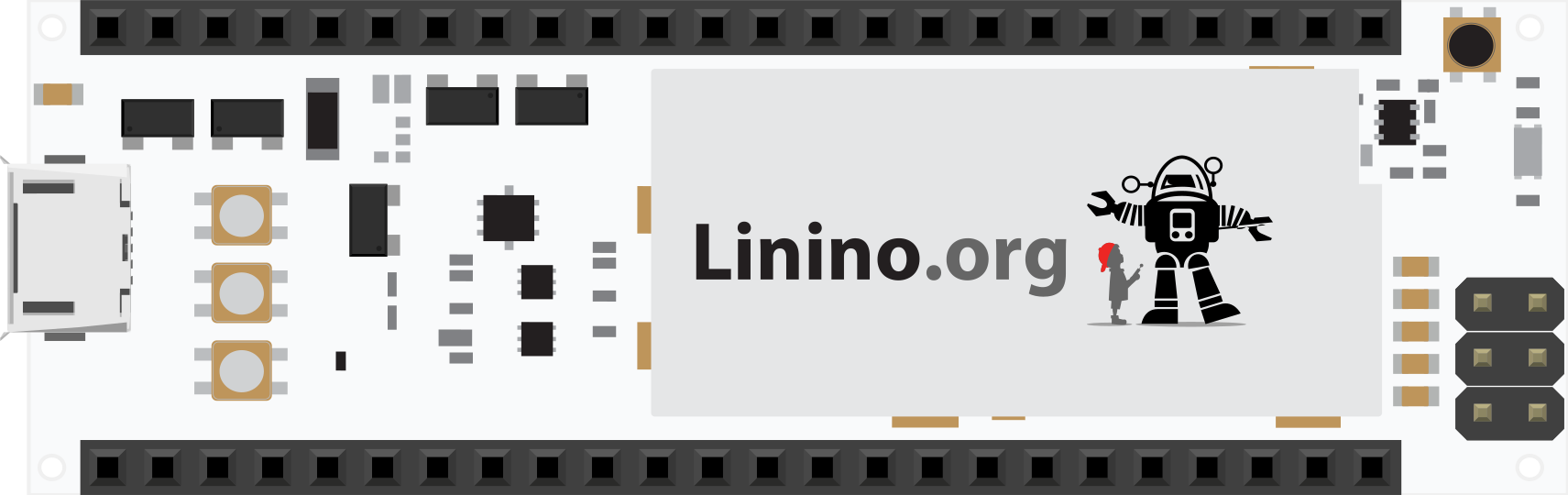
 Design with linino one in Cirkit Designer
Introduction
The Linino One is an Arduino-compatible development board manufactured by Linino. It integrates Wi-Fi connectivity, making it an excellent choice for Internet of Things (IoT) applications. The board combines the ease of Arduino programming with the power of a Linux-based system, enabling developers to create robust and connected projects. With its powerful processor, multiple I/O pins, and support for various programming environments, the Linino One is a versatile tool for both beginners and experienced developers.
Explore Projects Built with linino one
 Open Project in Cirkit Designer
 Open Project in Cirkit Designer
 Open Project in Cirkit Designer
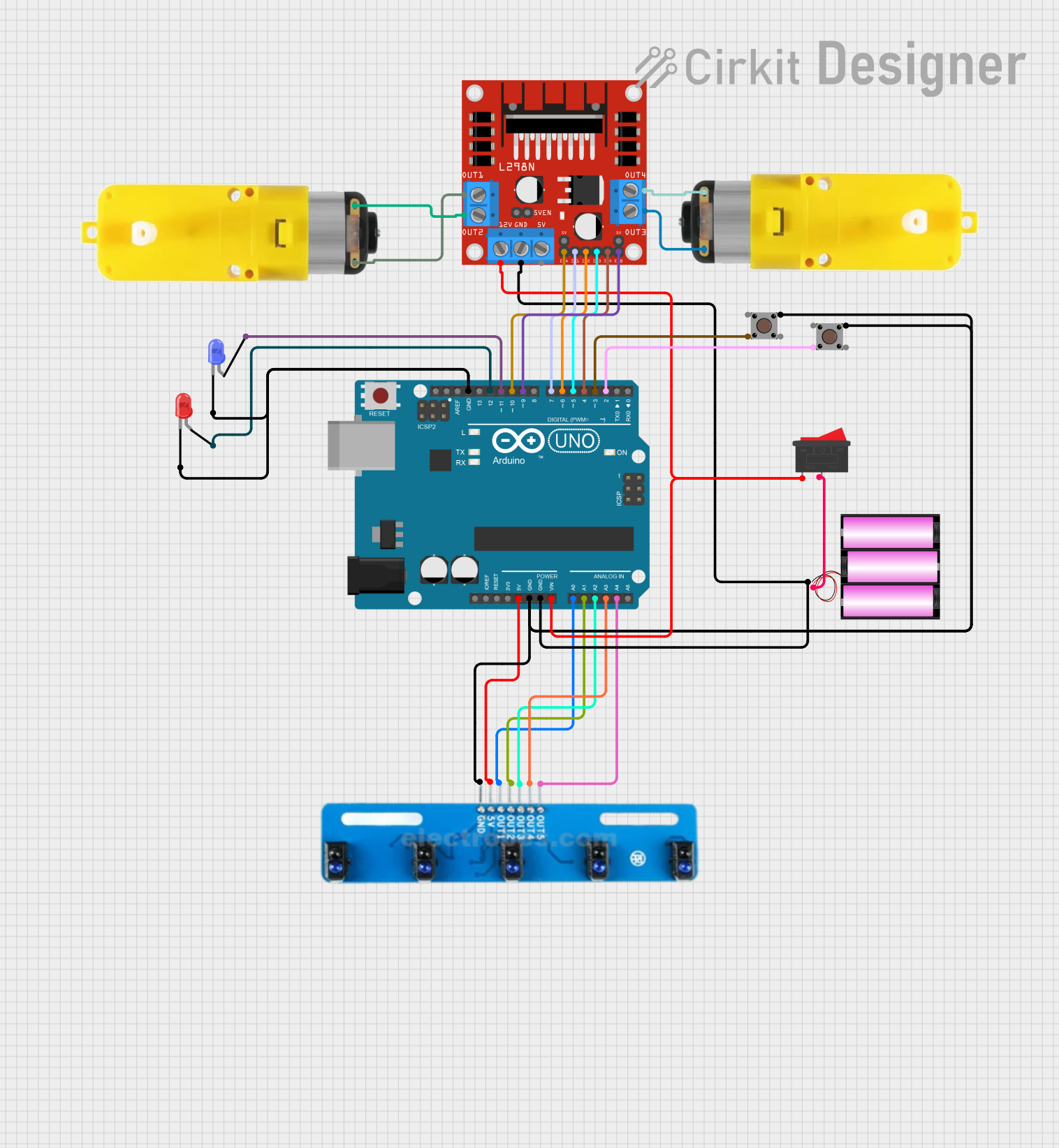 Open Project in Cirkit Designer
Explore Projects Built with linino one
Open Project in Cirkit DesignerOpen Project in Cirkit DesignerOpen Project in Cirkit DesignerOpen Project in Cirkit DesignerCommon Applications and Use Cases
- IoT devices and smart home automation
- Remote monitoring and control systems
- Data logging and cloud integration
- Prototyping connected devices
- Educational projects involving wireless communication
Technical Specifications
The Linino One is equipped with a range of features that make it suitable for IoT and embedded applications. Below are its key technical details:
Key Technical Details
| Specification | Value |
|---|---|
| Processor | Atheros AR9331 (MIPS 24Kc, 400 MHz) |
| Microcontroller | ATmega32u4 (Arduino-compatible) |
| Operating Voltage | 5V |
| Input Voltage (recommended) | 7-12V |
| Digital I/O Pins | 20 (7 PWM outputs) |
| Analog Input Pins | 12 |
| Flash Memory | 32 MB (Linux side) + 32 KB (ATmega32u4) |
| RAM | 64 MB DDR2 (Linux side) + 2.5 KB (ATmega32u4) |
| Wi-Fi | IEEE 802.11 b/g/n |
| USB Ports | 1 Micro-USB, 1 USB Host |
| Ethernet | 10/100 Mbps |
| Clock Speed | 16 MHz (ATmega32u4) + 400 MHz (AR9331) |
| Dimensions | 68.6 mm x 53.4 mm |
Pin Configuration and Descriptions
The Linino One features a variety of pins for digital and analog input/output. Below is the pin configuration:
Digital Pins
| Pin Number | Functionality |
|---|---|
| D0-D13 | General-purpose digital I/O |
| D3, D5, D6, D9, D10, D11 | PWM output |
| D0, D1 | UART (Serial communication) |
| D2 | External interrupt |
| D13 | Built-in LED |
Analog Pins
| Pin Number | Functionality |
|---|---|
| A0-A11 | Analog input (10-bit resolution) |
Power Pins
| Pin Name | Description |
|---|---|
| VIN | Input voltage to the board |
| 5V | Regulated 5V output |
| 3.3V | Regulated 3.3V output |
| GND | Ground |
Usage Instructions
The Linino One is designed to be user-friendly and versatile. Below are the steps and best practices for using the board in your projects.
How to Use the Linino One in a Circuit
Powering the Board:
- Use a Micro-USB cable to power the board via a computer or USB adapter.
- Alternatively, supply 7-12V to the VIN pin or the DC power jack.
Programming the Board:
- The Linino One can be programmed using the Arduino IDE. Select "Linino One" as the board type in the IDE.
- Connect the board to your computer via the Micro-USB port and upload your sketch.
Wi-Fi Configuration:
- The Linino One runs a Linux-based system (OpenWrt). Access the Linux side via SSH to configure Wi-Fi settings.
- Use the command
wifi detectto scan for networks and configure the/etc/config/wirelessfile for your network.
Connecting Sensors and Actuators:
- Use the digital and analog pins to connect sensors and actuators.
- Ensure that the voltage and current requirements of your components are compatible with the Linino One.
Important Considerations and Best Practices
- Power Supply: Avoid exceeding the recommended input voltage (7-12V) to prevent damage to the board.
- Wi-Fi Antenna: Ensure the board is in a location with good Wi-Fi signal strength for reliable connectivity.
- Linux Side: Familiarize yourself with basic Linux commands to fully utilize the board's capabilities.
- Pin Usage: Avoid using the same pin for multiple functions simultaneously to prevent conflicts.
Example: Connecting to an Arduino UNO
The Linino One can communicate with an Arduino UNO via serial communication. Below is an example Arduino sketch for the UNO to send data to the Linino One:
// Arduino UNO: Send data to Linino One via Serial
void setup() {
  Serial.begin(9600); // Initialize serial communication at 9600 baud
}

void loop() {
  Serial.println("Hello from Arduino UNO!"); // Send a message
  delay(1000); // Wait for 1 second
}
On the Linino One, you can use the following Python script (running on the Linux side) to read the data:
import serial
Open the serial port connected to the Arduino UNO
ser = serial.Serial('/dev/ttyATH0', 9600) # Adjust port as needed
while True: if ser.in_waiting > 0: # Check if data is available data = ser.readline().decode('utf-8').strip() print(f"Received: {data}") # Print the received data
Troubleshooting and FAQs
Common Issues and Solutions
The board is not detected by the Arduino IDE:
- Ensure the correct board type ("Linino One") and port are selected in the IDE.
- Check the USB cable for proper connection and functionality.
Wi-Fi connectivity issues:
- Verify the Wi-Fi credentials in the
/etc/config/wirelessfile. - Ensure the board is within range of the Wi-Fi router.
- Verify the Wi-Fi credentials in the
Sketch upload fails:
- Press the reset button on the board before uploading the sketch.
- Check for conflicting processes on the Linux side that may interfere with the USB port.
Linux side is unresponsive:
- Restart the board by pressing the reset button.
- If the issue persists, reflash the firmware using the official Linino tools.
FAQs
Q: Can I use the Linino One without Wi-Fi?
A: Yes, the Linino One can function as a standard Arduino-compatible board without using its Wi-Fi capabilities.
Q: How do I update the firmware on the Linino One?
A: Firmware updates can be performed via the Linux side using the sysupgrade command. Refer to the official Linino documentation for detailed instructions.
Q: Is the Linino One compatible with Arduino shields?
A: Yes, the Linino One is compatible with most Arduino shields, provided they operate at 5V.
Q: Can I use Python to program the Linino One?
A: Yes, the Linux side of the Linino One supports Python, allowing you to write and execute Python scripts.
This concludes the documentation for the Linino One. For further assistance, refer to the official Linino resources or community forums.