How to Use Adafruit MCP4725 Breakout Board - 12-Bit DAC: Examples, Pinouts, and Specs
Introduction
The Adafruit MCP4725 is a digital-to-analog converter (DAC) breakout board that provides a 12-bit resolution. This means it can convert a digital value into one of 4096 (2^12) different analog voltage levels. DACs are commonly used in applications where an accurate analog output is required, such as in audio equipment, signal generation, and fine control of actuators.
Common applications of the MCP4725 include:
- Generating audio signals
- Creating a variable voltage reference
- Simulating sensor outputs
- Controlling the intensity of LEDs
- Driving analog circuits that require precise voltage control
Explore Projects Built with Adafruit MCP4725 Breakout Board - 12-Bit DAC

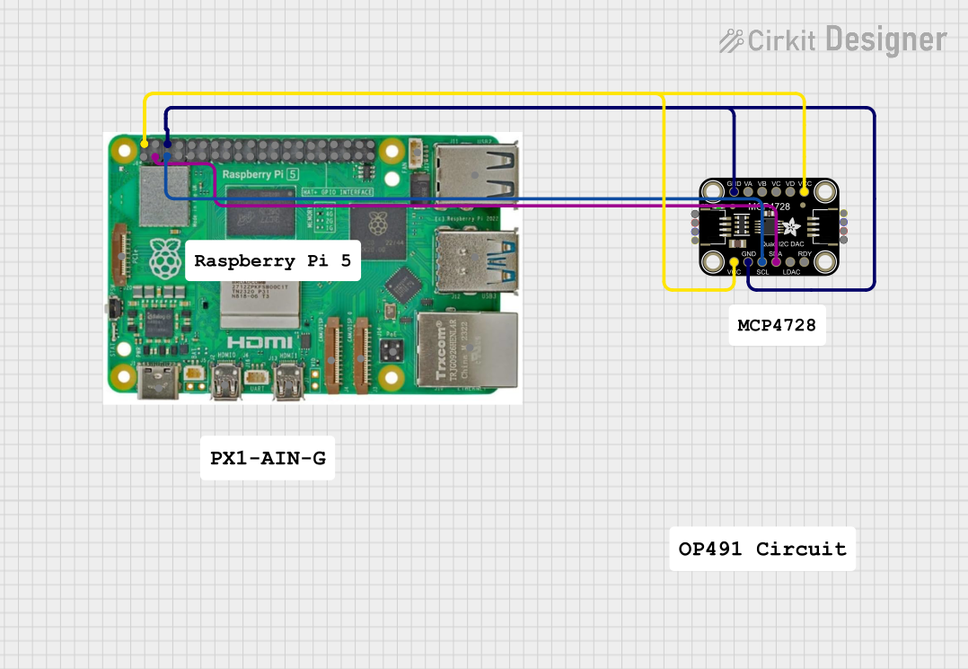
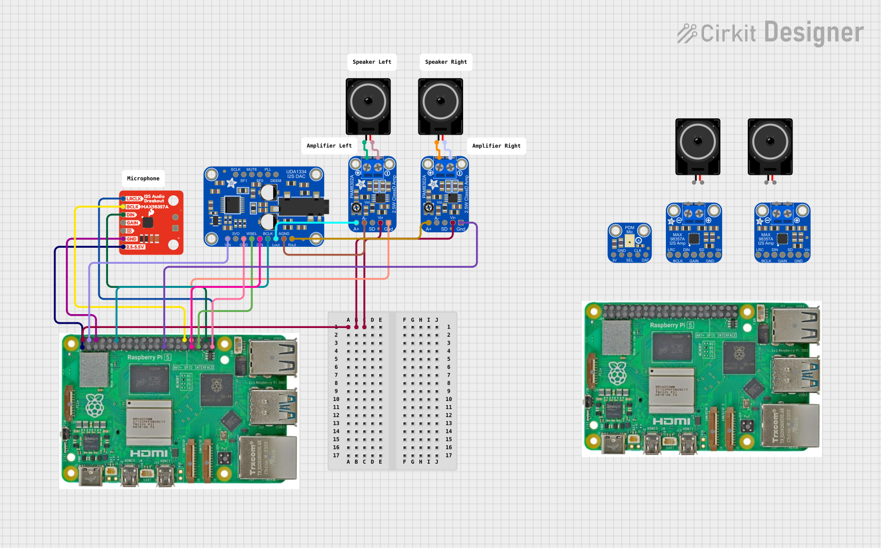
Explore Projects Built with Adafruit MCP4725 Breakout Board - 12-Bit DAC
Technical Specifications
Key Technical Details
- Resolution: 12-bit
- Interface: I2C
- Supply Voltage: 2.7V to 5.5V
- Output Voltage: 0V to VCC
- Maximum Output Current: 25 mA
- Settling Time: 6 µs (typical)
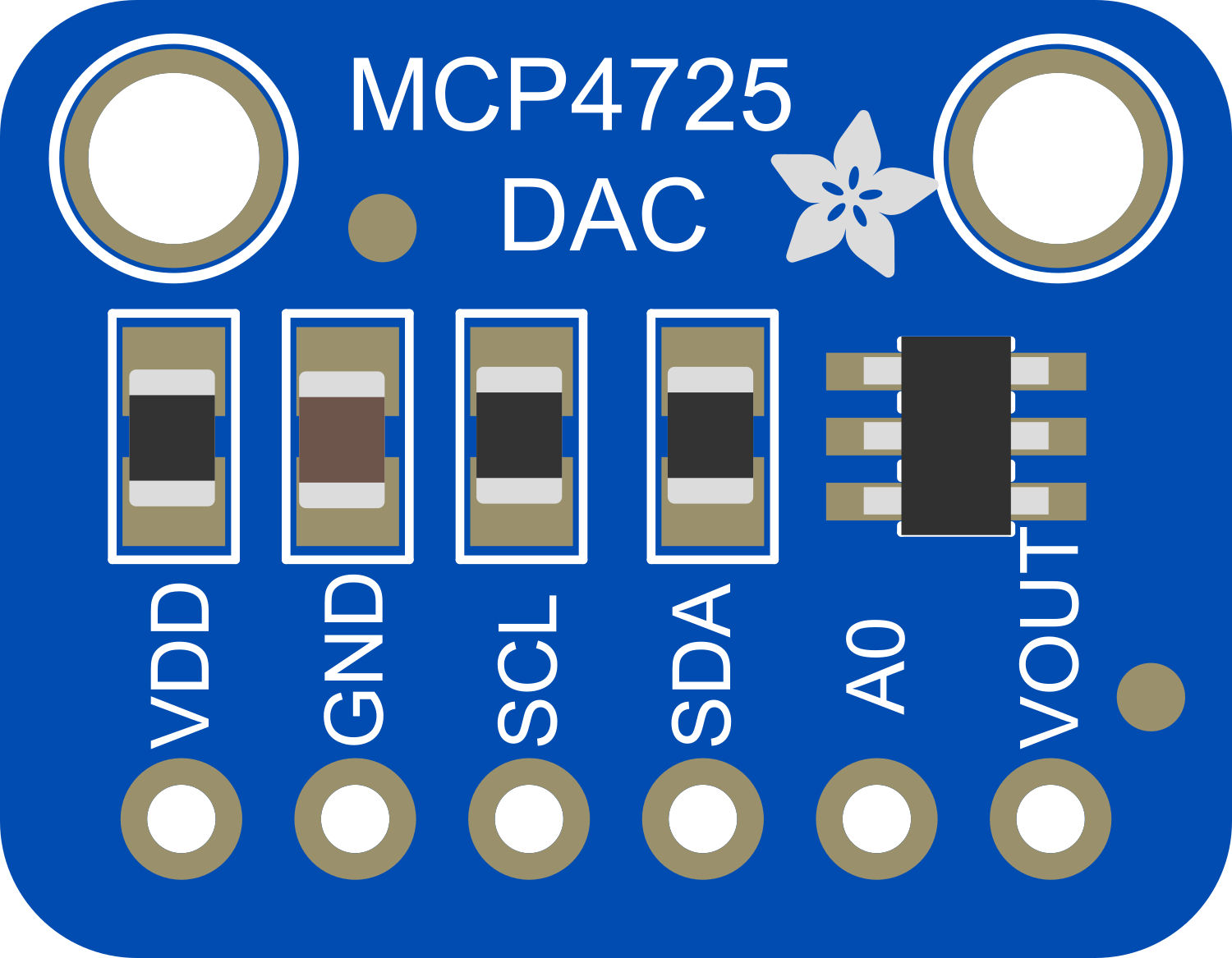
Pin Configuration and Descriptions
| Pin Number | Name | Description |
|---|---|---|
| 1 | VDD | Power supply (2.7V to 5.5V) |
| 2 | GND | Ground |
| 3 | SDA | I2C Data |
| 4 | SCL | I2C Clock |
| 5 | A0 | Address select pin |
Usage Instructions
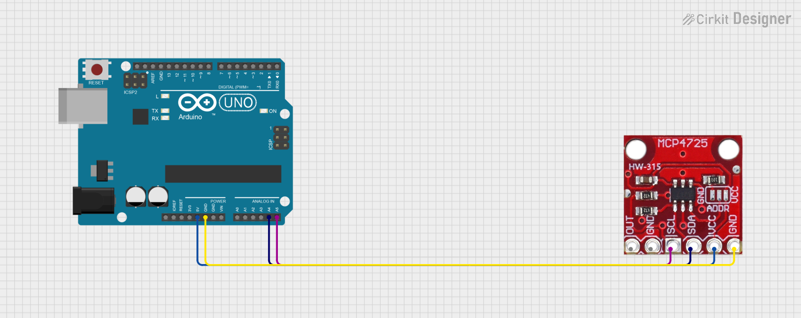
Connecting to a Microcontroller
- Connect VDD to the 5V (or 3.3V) output on your microcontroller.
- Connect GND to the ground on your microcontroller.
- Connect SDA to the I2C data line (A4 on Arduino UNO).
- Connect SCL to the I2C clock line (A5 on Arduino UNO).
- The A0 pin can be connected to ground or VDD to change the I2C address if multiple devices are used.
Important Considerations and Best Practices
- Ensure that the power supply voltage matches the logic level of your microcontroller to avoid damage.
- Use pull-up resistors on the SDA and SCL lines if your microcontroller does not have built-in pull-ups.
- Avoid running high-speed I2C communication as it may affect the DAC performance.
- When using multiple MCP4725 modules, make sure each has a unique I2C address.
Example Arduino Code
#include <Wire.h>
#include <Adafruit_MCP4725.h>

Adafruit_MCP4725 dac;

void setup() {
  Wire.begin(); // Initialize I2C
  dac.begin(0x60); // Initialize MCP4725, default address 0x60
}

void loop() {
  uint16_t outputValue = 2048; // Midpoint of 12-bit range (0-4095)
  dac.setVoltage(outputValue, false); // Set DAC output to midpoint
  delay(1000); // Wait for 1 second
  // Repeat with different values as needed
}
Troubleshooting and FAQs
Common Issues
- No Output Voltage: Ensure that the MCP4725 is properly powered and that the I2C lines are correctly connected.
- Inaccurate Output Voltage: Check if the power supply is stable and within the specified range.
- I2C Communication Error: Verify that the pull-up resistors are in place and that there are no shorts on the I2C lines.
Solutions and Tips
- If you encounter noise in the output, adding a decoupling capacitor between VDD and GND near the MCP4725 may help.
- For precise applications, calibrate the output by measuring the voltage and adjusting the digital value accordingly.
- Use the
dac.setVoltage(value, true);function to update the output voltage with the internal EEPROM, which will retain the voltage output after power cycling.
FAQs
Q: Can I use the MCP4725 with a 3.3V system? A: Yes, the MCP4725 is compatible with 3.3V systems. Make sure to connect VDD to 3.3V.
Q: How do I change the I2C address of the MCP4725? A: The A0 pin can be connected to GND or VDD to change the address. The default address is 0x60, and connecting A0 to VDD changes it to 0x61.
Q: Can the MCP4725 output negative voltages? A: No, the MCP4725 can only output voltages from 0V to VCC. For negative voltages, additional circuitry is required.
Q: How many MCP4725 devices can I connect to a single I2C bus? A: You can connect up to two MCP4725 devices to a single I2C bus by using different addresses for each device.