How to Use tmp117: Examples, Pinouts, and Specs
Introduction
The TMP117 is a high-accuracy digital temperature sensor designed for precision temperature measurements. It communicates via the I2C interface, making it easy to integrate into microcontroller-based systems. With a wide temperature range of -55°C to +150°C and an impressive accuracy of ±0.1°C, the TMP117 is ideal for applications requiring precise thermal monitoring. These include industrial automation, medical devices, HVAC systems, and consumer electronics.
Explore Projects Built with tmp117
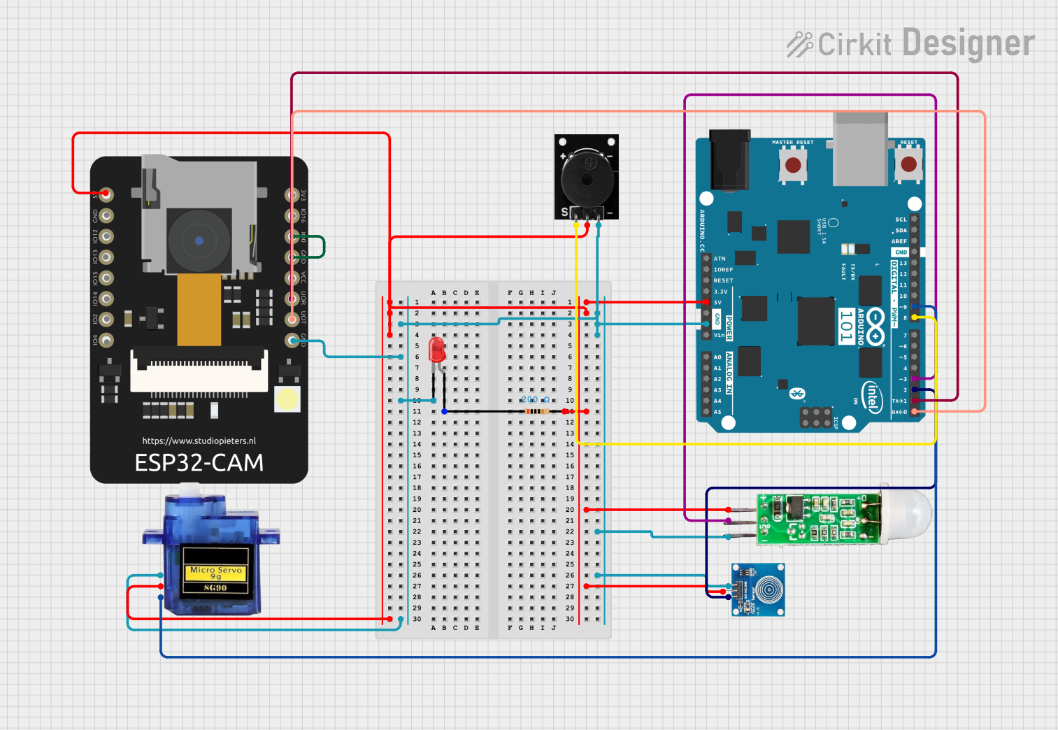
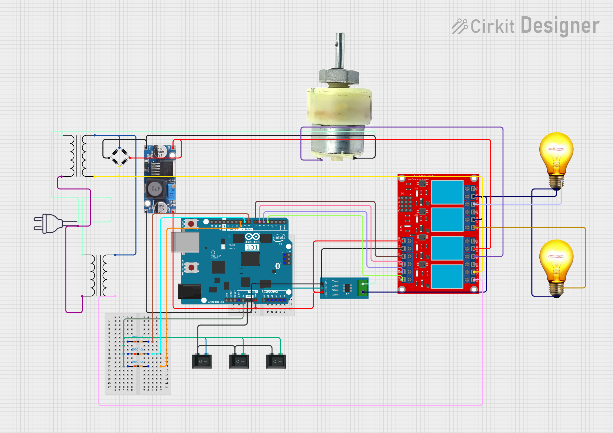
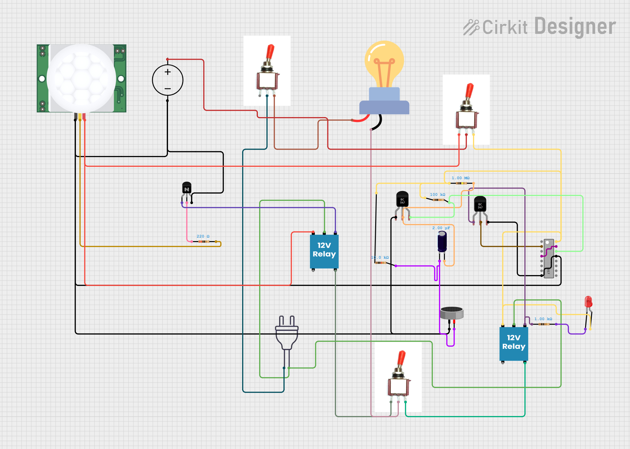
Explore Projects Built with tmp117
Technical Specifications
The TMP117 offers robust performance and flexibility for temperature sensing applications. Below are its key technical details:
Key Specifications
| Parameter | Value |
|---|---|
| Temperature Range | -55°C to +150°C |
| Accuracy | ±0.1°C (from -20°C to +50°C) |
| Supply Voltage (VDD) | 1.8V to 5.5V |
| Communication Interface | I2C (up to 400 kHz) |
| Resolution | 16 bits |
| Current Consumption | 3.5 µA (typical, 1 Hz mode) |
| Operating Modes | Continuous, Shutdown |
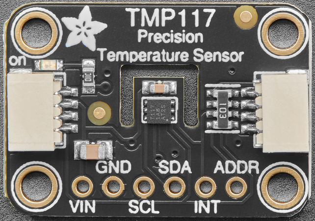
Pin Configuration
The TMP117 is typically available in a 6-pin WSON package. Below is the pinout description:
| Pin Number | Pin Name | Description |
|---|---|---|
| 1 | SDA | I2C Data Line |
| 2 | SCL | I2C Clock Line |
| 3 | ALERT | Interrupt/Alert Output (active low, open-drain) |
| 4 | GND | Ground |
| 5 | VDD | Power Supply (1.8V to 5.5V) |
| 6 | ADD0 | I2C Address Selection (connect to GND or VDD) |
Usage Instructions
The TMP117 is straightforward to use in a circuit, thanks to its I2C interface. Below are the steps and considerations for integrating the TMP117 into your design:
Circuit Connection
- Power Supply: Connect the VDD pin to a 1.8V to 5.5V power source and the GND pin to ground.
- I2C Lines: Connect the SDA and SCL pins to the corresponding I2C lines of your microcontroller. Use pull-up resistors (typically 4.7 kΩ) on both lines.
- Address Selection: Use the ADD0 pin to set the I2C address:
- Connect ADD0 to GND for address
0x48. - Connect ADD0 to VDD for address
0x49.
- Connect ADD0 to GND for address
- Optional Alert Pin: The ALERT pin can be used for interrupt-driven temperature monitoring. Connect it to a GPIO pin on your microcontroller if needed.
Example Code for Arduino UNO
Below is an example of how to use the TMP117 with an Arduino UNO. This code reads the temperature and prints it to the Serial Monitor.
#include <Wire.h>

// TMP117 I2C address (default is 0x48 if ADD0 is connected to GND)
#define TMP117_ADDRESS 0x48

// TMP117 register addresses
#define TMP117_TEMP_RESULT 0x00

void setup() {
  Wire.begin(); // Initialize I2C communication
  Serial.begin(9600); // Start Serial communication for debugging
  Serial.println("TMP117 Temperature Sensor Example");
}

void loop() {
  float temperature = readTemperature();
  Serial.print("Temperature: ");
  Serial.print(temperature);
  Serial.println(" °C");
  delay(1000); // Wait 1 second before the next reading
}

float readTemperature() {
  Wire.beginTransmission(TMP117_ADDRESS);
  Wire.write(TMP117_TEMP_RESULT); // Point to the temperature result register
  Wire.endTransmission();

  Wire.requestFrom(TMP117_ADDRESS, 2); // Request 2 bytes of data
  if (Wire.available() == 2) {
    int16_t rawData = (Wire.read() << 8) | Wire.read(); // Combine MSB and LSB
    return rawData * 0.0078125; // Convert to Celsius (0.0078125°C/LSB)
  } else {
    Serial.println("Error: No data received!");
    return NAN; // Return Not-a-Number if data is unavailable
  }
}
Best Practices
- Use decoupling capacitors (e.g., 0.1 µF) near the VDD pin to reduce noise.
- Ensure proper pull-up resistors are used on the I2C lines.
- Avoid long I2C lines to minimize signal degradation.
- If using the ALERT pin, configure it in your microcontroller's interrupt settings for efficient monitoring.
Troubleshooting and FAQs
Common Issues
No I2C Communication:
- Ensure the TMP117 is powered correctly (check VDD and GND connections).
- Verify the I2C address matches your configuration (check ADD0 pin).
- Check for proper pull-up resistors on SDA and SCL lines.
Incorrect Temperature Readings:
- Confirm the TMP117 is within its operating temperature range.
- Ensure the sensor is not exposed to sudden temperature changes or airflow.
ALERT Pin Not Functioning:
- Verify the ALERT pin is configured correctly in your microcontroller.
- Check if the TMP117's alert thresholds are set properly.
FAQs
Q: Can the TMP117 operate at 3.3V?
A: Yes, the TMP117 supports a supply voltage range of 1.8V to 5.5V, so 3.3V is within its operating range.
Q: How do I set temperature alert thresholds?
A: The TMP117 has dedicated registers for high and low temperature limits. Use the I2C interface to configure these registers.
Q: What is the maximum I2C clock speed supported?
A: The TMP117 supports I2C clock speeds up to 400 kHz.
Q: Can I use multiple TMP117 sensors on the same I2C bus?
A: Yes, you can use up to two TMP117 sensors by configuring their ADD0 pins to different states (GND or VDD) to assign unique I2C addresses.
By following this documentation, you can effectively integrate and use the TMP117 in your projects.