How to Use Rcd switch: Examples, Pinouts, and Specs
Introduction
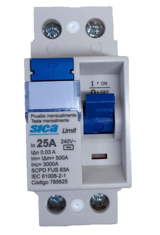
A Residual Current Device (RCD) switch is a critical safety component in electrical systems. It is designed to protect users from electric shocks and prevent electrical fires by disconnecting the circuit whenever it detects an imbalance between the live and neutral wires. This imbalance typically indicates a leakage current, which could be caused by a fault or accidental contact with a live wire.
Explore Projects Built with Rcd switch


Explore Projects Built with Rcd switch
Common Applications and Use Cases
- Residential Electrical Systems: Protects household circuits and appliances.
- Industrial Environments: Ensures worker safety in high-power equipment setups.
- Outdoor Installations: Provides protection for garden equipment, outdoor lighting, and power tools.
- Portable Devices: Used in portable power distribution units for added safety.
Technical Specifications
The RCD switch is available in various configurations depending on the application. Below are the general technical specifications:
Key Technical Details
- Rated Voltage: 230V AC (single-phase) or 400V AC (three-phase)
- Rated Current: 16A, 32A, 63A (varies by model)
- Trip Sensitivity: 10mA, 30mA, or 100mA
- Trip Time: ≤ 300ms
- Frequency: 50/60 Hz
- Operating Temperature: -5°C to 40°C
- Standards Compliance: IEC 61008, IEC 61009
Pin Configuration and Descriptions
The RCD switch typically has four terminals for single-phase models and additional terminals for three-phase models. Below is the pin configuration for a single-phase RCD switch:
| Pin Number | Label | Description |
|---|---|---|
| 1 | L (Input) | Live wire input from the power source |
| 2 | N (Input) | Neutral wire input from the power source |
| 3 | L (Output) | Live wire output to the load |
| 4 | N (Output) | Neutral wire output to the load |
For three-phase RCD switches, additional terminals (L2, L3) are included for the extra live wires.
Usage Instructions
How to Use the RCD Switch in a Circuit
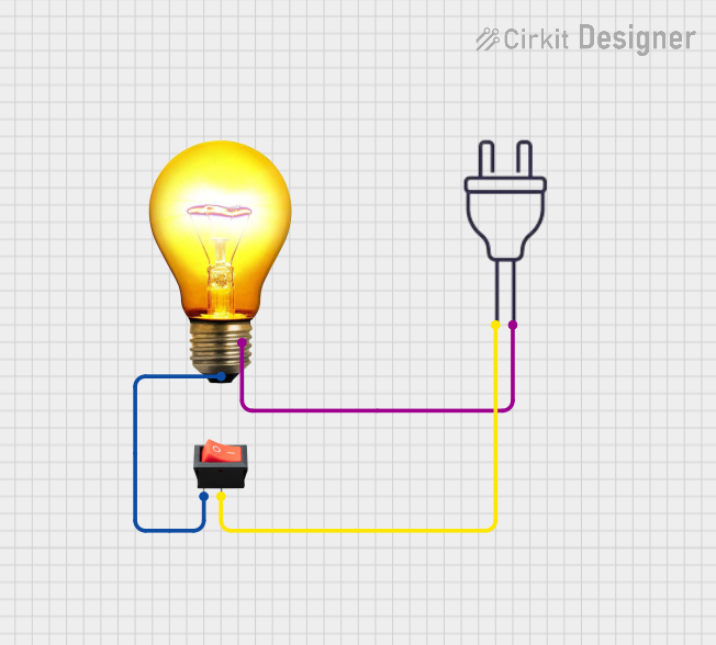
- Identify the Input and Output Terminals: Connect the live and neutral wires from the power source to the input terminals (L and N). Connect the load to the output terminals.
- Ensure Proper Grounding: Verify that the circuit is properly grounded to enhance safety.
- Test the RCD Switch: Use the built-in test button to simulate a fault condition. Pressing the test button should trip the switch, disconnecting the circuit.
- Reset After Tripping: If the RCD trips, identify and resolve the fault before resetting the switch.
Important Considerations and Best Practices
- Select the Correct Sensitivity: Use a 30mA RCD for personal protection and a 100mA RCD for fire prevention.
- Avoid Overloading: Ensure the connected load does not exceed the rated current of the RCD.
- Regular Testing: Test the RCD switch monthly using the test button to ensure proper functionality.
- Use in Dry Conditions: Avoid installing the RCD in areas prone to moisture unless it is specifically rated for such environments.
Example: Connecting an RCD Switch to an Arduino UNO
While RCD switches are not directly controlled by microcontrollers like the Arduino UNO, they can be monitored using a current sensor. Below is an example of how to monitor the current in a circuit protected by an RCD switch:
/*
  Example: Monitoring Current in an RCD-Protected Circuit
  This code uses an ACS712 current sensor to measure current in a circuit.
  The Arduino reads the sensor output and prints the current value to the
  Serial Monitor.

  Note: This setup does not control the RCD switch but monitors the circuit.
*/

const int sensorPin = A0; // Analog pin connected to the ACS712 sensor
const float sensitivity = 0.185; // Sensitivity for 5A ACS712 (V/A)
const float offsetVoltage = 2.5; // Sensor output at 0A (V)

void setup() {
  Serial.begin(9600); // Initialize serial communication
}

void loop() {
  int sensorValue = analogRead(sensorPin); // Read sensor value
  float voltage = (sensorValue / 1023.0) * 5.0; // Convert to voltage
  float current = (voltage - offsetVoltage) / sensitivity; // Calculate current

  Serial.print("Current: ");
  Serial.print(current, 3); // Print current in Amperes
  Serial.println(" A");

  delay(1000); // Wait 1 second before next reading
}
Troubleshooting and FAQs
Common Issues and Solutions
RCD Switch Does Not Trip During Testing
- Cause: Faulty test button or internal mechanism.
- Solution: Replace the RCD switch if it fails the test.
Frequent Tripping
- Cause: Overloaded circuit, faulty appliances, or moisture ingress.
- Solution: Inspect the circuit for faults, reduce the load, or replace damaged appliances.
RCD Does Not Reset
- Cause: Persistent fault in the circuit.
- Solution: Identify and resolve the fault before attempting to reset.
RCD Trips Without Apparent Cause
- Cause: Nuisance tripping due to electromagnetic interference or minor leakage currents.
- Solution: Use an RCD with a higher trip sensitivity (e.g., 100mA) if appropriate.
FAQs
Q: Can I use an RCD switch with a generator?
- A: Yes, but ensure the generator is properly grounded and compatible with the RCD.
Q: How often should I test my RCD switch?
- A: Test the RCD switch at least once a month using the test button.
Q: Can an RCD switch protect against overcurrent?
- A: No, an RCD switch only detects leakage currents. Use a circuit breaker for overcurrent protection.
Q: What is the difference between an RCD and an RCCB?
- A: Both are similar devices, but RCCB (Residual Current Circuit Breaker) is a specific type of RCD designed for residential use.