How to Use SIM MODULE: Examples, Pinouts, and Specs
Introduction
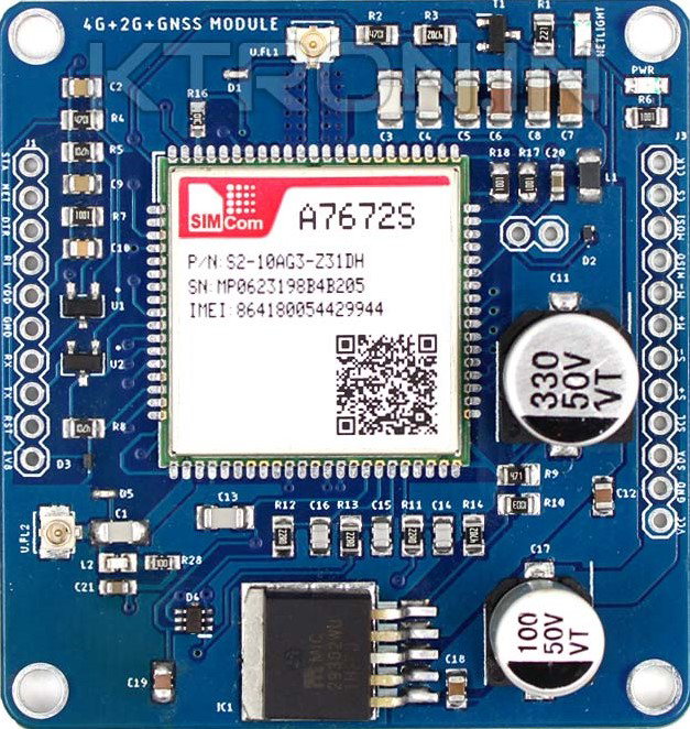
The SIM MODULE (SIMCOMA7672S), manufactured by KETRON, is a compact and versatile component designed to enable cellular connectivity and authentication on mobile networks. It stores subscriber information, such as the International Mobile Subscriber Identity (IMSI) and authentication keys, which are essential for communication with mobile network operators. This module is widely used in IoT devices, mobile phones, and embedded systems requiring cellular communication.
Explore Projects Built with SIM MODULE


Explore Projects Built with SIM MODULE
Common Applications and Use Cases
- Mobile phones and smartphones for cellular connectivity
- IoT devices for remote monitoring and control
- GPS trackers for real-time location updates
- Smart meters for utility data transmission
- Industrial automation systems requiring remote communication
- Emergency alert systems and telematics
Technical Specifications
The SIMCOMA7672S module is designed to meet the requirements of modern cellular communication systems. Below are its key technical specifications:
General Specifications
| Parameter | Value |
|---|---|
| Manufacturer | KETRON |
| Part ID | SIMCOMA7672S |
| Network Compatibility | GSM, GPRS, 3G, 4G LTE |
| Operating Voltage | 3.3V to 4.2V |
| Power Consumption | Idle: 10mA, Active: 500mA |
| Operating Temperature | -40°C to +85°C |
| Dimensions | 30mm x 20mm x 2.5mm |
Pin Configuration and Descriptions
The SIMCOMA7672S module has a standard pinout for easy integration into various systems. Below is the pin configuration:
| Pin Number | Pin Name | Description |
|---|---|---|
| 1 | VCC | Power supply input (3.3V to 4.2V) |
| 2 | GND | Ground connection |
| 3 | TXD | UART Transmit Data (to microcontroller RX) |
| 4 | RXD | UART Receive Data (to microcontroller TX) |
| 5 | RST | Reset pin (active low) |
| 6 | NET_STATUS | Network status indicator (high = connected) |
| 7 | SIM_DET | SIM card detection (high = SIM inserted) |
| 8 | ANT | Antenna connection |
Usage Instructions
How to Use the SIMCOMA7672S in a Circuit
- Power Supply: Connect the VCC pin to a regulated 3.3V to 4.2V power source and the GND pin to the ground of your circuit.
- UART Communication: Connect the TXD and RXD pins to the corresponding RX and TX pins of your microcontroller or development board (e.g., Arduino UNO).
- Antenna: Attach an external antenna to the ANT pin for optimal signal reception.
- SIM Card: Insert a valid SIM card into the module's SIM card slot.
- Reset: Use the RST pin to reset the module if needed (active low).
- Network Status: Monitor the NET_STATUS pin to check the module's connection to the network.
Important Considerations and Best Practices
- Ensure the power supply is stable and within the specified voltage range to avoid damage to the module.
- Use a level shifter if interfacing with a 5V microcontroller, as the module operates at 3.3V logic levels.
- Place the antenna away from noise sources to improve signal quality.
- Handle the SIM card carefully to avoid damage to the contacts.
- Use proper decoupling capacitors near the VCC pin to reduce noise and ensure stable operation.
Example: Connecting to an Arduino UNO
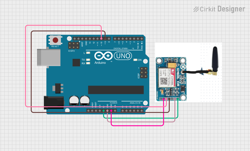
Below is an example of how to connect the SIMCOMA7672S module to an Arduino UNO and send an SMS:
Circuit Connections
| SIMCOMA7672S Pin | Arduino UNO Pin |
|---|---|
| VCC | 3.3V |
| GND | GND |
| TXD | Pin 10 (RX) |
| RXD | Pin 11 (TX) |
| RST | Pin 12 |
Arduino Code
#include <SoftwareSerial.h>

// Define RX and TX pins for SoftwareSerial
SoftwareSerial simModule(10, 11); // RX = Pin 10, TX = Pin 11

void setup() {
  // Initialize serial communication with the SIM module
  simModule.begin(9600);
  Serial.begin(9600); // For debugging via Serial Monitor

  // Wait for the module to initialize
  delay(1000);
  Serial.println("Initializing SIM Module...");

  // Send AT command to check communication
  simModule.println("AT");
  delay(1000);
  while (simModule.available()) {
    Serial.write(simModule.read()); // Print response to Serial Monitor
  }

  // Send SMS command
  simModule.println("AT+CMGF=1"); // Set SMS mode to text
  delay(1000);
  simModule.println("AT+CMGS=\"+1234567890\""); // Replace with recipient's number
  delay(1000);
  simModule.print("Hello, this is a test SMS from SIMCOMA7672S!"); // SMS content
  delay(1000);
  simModule.write(26); // Send Ctrl+Z to send the SMS
  Serial.println("SMS Sent!");
}

void loop() {
  // No actions in loop
}
Troubleshooting and FAQs
Common Issues and Solutions
Module Not Responding to AT Commands
- Ensure the power supply is stable and within the specified range.
- Verify the UART connections (TXD to RX and RXD to TX).
- Check if the SIM card is properly inserted and detected.
No Network Connection
- Confirm that the antenna is securely connected and positioned correctly.
- Ensure the SIM card is active and has sufficient balance for network services.
- Check the NET_STATUS pin to verify network connectivity.
SMS Not Sending
- Verify the recipient's phone number format (e.g., include the country code).
- Ensure the module is registered on the network (use the "AT+CREG?" command to check).
FAQs
Q1: Can the SIMCOMA7672S module work with 5V microcontrollers?
A1: Yes, but you must use a level shifter to convert the 5V logic levels to 3.3V.
Q2: What type of antenna should I use?
A2: Use a 4G LTE-compatible antenna for optimal performance.
Q3: How do I check the signal strength?
A3: Use the "AT+CSQ" command to query the signal strength. The module will return a value indicating the signal quality.
Q4: Can I use this module for data communication?
A4: Yes, the SIMCOMA7672S supports GPRS, 3G, and 4G LTE for data communication. Use appropriate AT commands to configure and initiate data sessions.