
How to Use usb relay 8 channel: Examples, Pinouts, and Specs
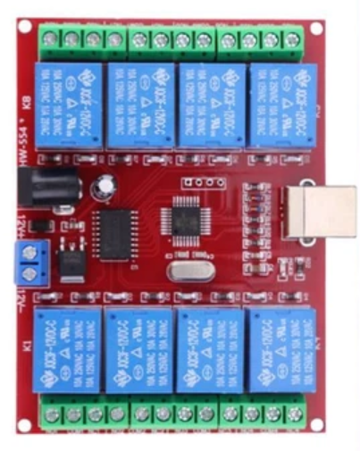
 Design with usb relay 8 channel in Cirkit Designer
Introduction
The USB Relay 8 Channel module, manufactured by Relay (Part ID: 8 Channel), is a versatile electronic component designed for controlling multiple devices through a USB interface. This module features 8 independent relay channels, allowing users to switch high-voltage loads safely and efficiently. It is commonly used in automation, home control systems, industrial equipment, and other applications requiring remote or computer-controlled switching.
Explore Projects Built with usb relay 8 channel
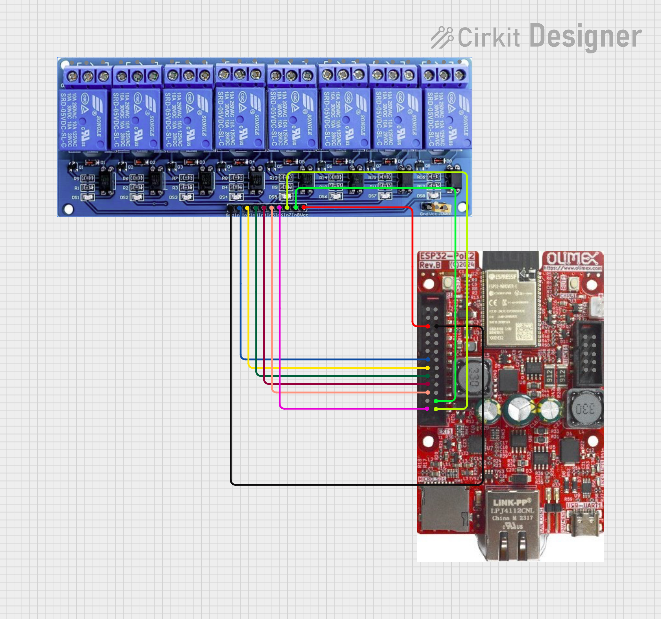 Open Project in Cirkit Designer
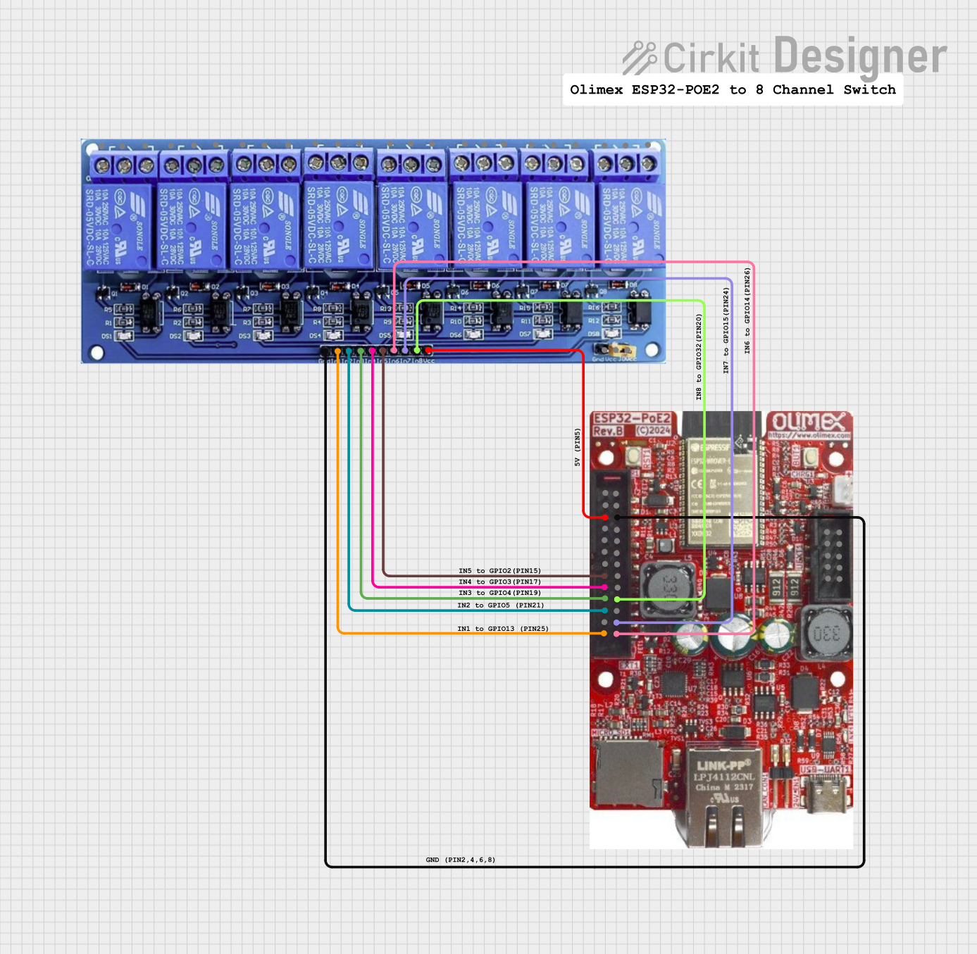 Open Project in Cirkit Designer
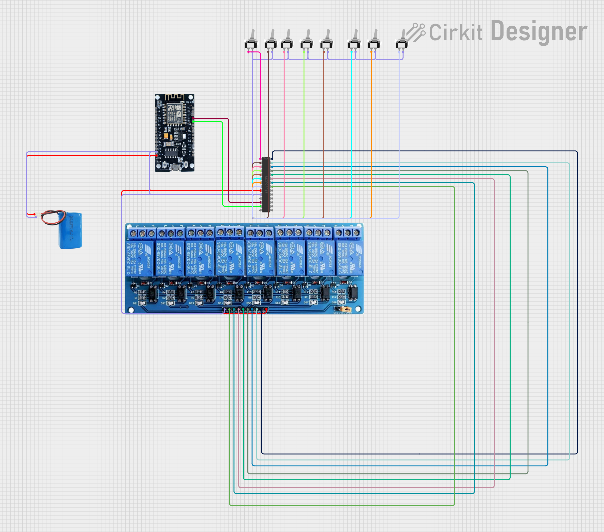 Open Project in Cirkit Designer
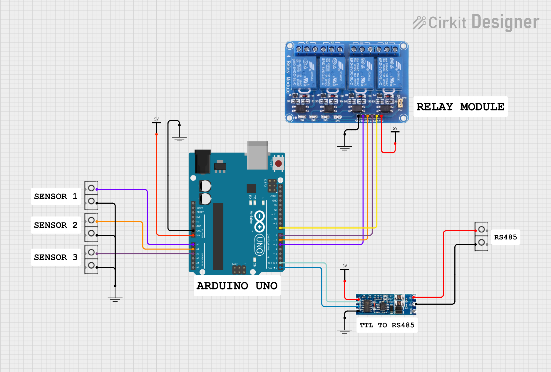 Open Project in Cirkit Designer
Explore Projects Built with usb relay 8 channel
Open Project in Cirkit DesignerOpen Project in Cirkit DesignerOpen Project in Cirkit DesignerOpen Project in Cirkit DesignerCommon Applications:
- Home automation (e.g., controlling lights, fans, or appliances)
- Industrial automation and control systems
- Laboratory equipment control
- IoT (Internet of Things) projects
- Prototyping and testing setups
Technical Specifications
Below are the key technical details of the USB Relay 8 Channel module:
| Parameter | Specification |
|---|---|
| Operating Voltage | 5V DC (via USB) |
| Relay Channels | 8 |
| Relay Type | SPDT (Single Pole Double Throw) |
| Maximum Load Voltage | 250V AC / 30V DC |
| Maximum Load Current | 10A |
| Communication Interface | USB 2.0 |
| Control Signal Logic | TTL-compatible |
| Dimensions | ~140mm x 90mm x 20mm |
| Operating Temperature | -40°C to 85°C |
Pin Configuration and Descriptions
The USB Relay 8 Channel module has the following key connections:
Relay Output Terminals
Each relay channel has three terminals: COM, NO, and NC.
| Terminal | Description |
|---|---|
| COM | Common terminal for the relay. Connect this to the input power or signal. |
| NO | Normally Open terminal. Connect this to the load for switching when activated. |
| NC | Normally Closed terminal. Connect this to the load for switching when inactive. |
USB Interface
The module includes a USB Type-B connector for communication and power. No external power supply is required as the module is powered directly via USB.
Usage Instructions
How to Use the USB Relay 8 Channel Module
Connect the Module to a Computer:
- Use a USB Type-B cable to connect the module to a computer or microcontroller with USB host capability.
- Ensure the appropriate drivers are installed (if required by the operating system).
Install Control Software:
- Use the manufacturer's software or a compatible open-source library to control the relays.
- For microcontroller-based control, ensure the USB communication library is configured.
Connect the Load:
- Identify the relay channel you want to use.
- Connect the load to the COM and NO terminals for normally open operation, or COM and NC for normally closed operation.
Control the Relays:
- Use the software or microcontroller to send commands to the module, activating or deactivating the desired relay channels.
Important Considerations and Best Practices
- Power Ratings: Ensure the connected load does not exceed the relay's maximum voltage and current ratings (250V AC / 30V DC, 10A).
- Isolation: The relays provide electrical isolation between the control circuit and the load. However, take precautions when working with high-voltage loads.
- USB Cable Length: Use a high-quality USB cable with a length of no more than 5 meters to ensure reliable communication.
- Driver Installation: Some operating systems may require specific drivers for the module. Refer to the manufacturer's documentation for details.
Example: Using with Arduino UNO
Although the USB Relay 8 Channel module is primarily designed for USB control, it can also be used with an Arduino UNO via USB communication. Below is an example of how to send commands to the module using the Arduino IDE:
#include <SoftwareSerial.h>

// Define RX and TX pins for software serial communication
SoftwareSerial usbRelay(10, 11); // RX = Pin 10, TX = Pin 11

void setup() {
  // Initialize serial communication with the USB relay module
  usbRelay.begin(9600); // Set baud rate to 9600
  Serial.begin(9600);   // For debugging via Serial Monitor

  // Example: Turn on relay channel 1
  usbRelay.write(0x01); // Send command to activate relay 1
  delay(1000);          // Wait for 1 second

  // Example: Turn off relay channel 1
  usbRelay.write(0x00); // Send command to deactivate relay 1
}

void loop() {
  // Add your custom logic here to control the relays
}
Note: Replace the
usbRelay.write()commands with the appropriate control codes for your specific module. Refer to the manufacturer's protocol documentation for details.
Troubleshooting and FAQs
Common Issues and Solutions
Relays Not Activating:
- Cause: Incorrect USB connection or missing drivers.
- Solution: Verify the USB cable connection and ensure the required drivers are installed.
Load Not Switching:
- Cause: Incorrect wiring of the load to the relay terminals.
- Solution: Double-check the wiring. Ensure the load is connected to the correct terminals (COM, NO, or NC).
Communication Errors:
- Cause: Faulty USB cable or incorrect baud rate.
- Solution: Use a high-quality USB cable and verify the baud rate matches the module's specifications.
Overheating Relays:
- Cause: Load exceeds the relay's maximum current rating.
- Solution: Ensure the load does not exceed 10A. Use an external relay or contactor for higher loads.
FAQs
Q1: Can I control the USB Relay 8 Channel module with a Raspberry Pi?
A1: Yes, the module can be controlled using a Raspberry Pi via USB. Use Python and a USB communication library (e.g., pyserial) to send commands to the module.
Q2: Does the module support simultaneous control of all 8 relays?
A2: Yes, all 8 relays can be controlled independently or simultaneously, depending on the commands sent.
Q3: Is the module compatible with macOS or Linux?
A3: Yes, the module is compatible with macOS and Linux. However, you may need to install additional drivers or use open-source libraries for communication.
Q4: Can I use the module without a computer?
A4: Yes, the module can be controlled by any microcontroller or device with USB host capability, such as an Arduino or Raspberry Pi.
By following this documentation, you can effectively integrate the USB Relay 8 Channel module into your projects and troubleshoot common issues with ease.