Cirkit Designer Logo
Cirkit Designer
Your all-in-one circuit design IDE
Home / 
Component Documentation

How to Use traffic light: Examples, Pinouts, and Specs

Image of traffic light
Cirkit Designer LogoDesign with traffic light in Cirkit Designer

Introduction

A traffic light is a signaling device that uses colored lights to control vehicle and pedestrian traffic at intersections. It typically features three lights: red, yellow, and green, which indicate stop, caution, and go, respectively. Traffic lights are essential for maintaining order and safety in road systems.

Explore Projects Built with traffic light

Use Cirkit Designer to design, explore, and prototype these projects online. Some projects support real-time simulation. Click "Open Project" to start designing instantly!
Arduino UNO Controlled Traffic Light System
Image of led traffic: A project utilizing traffic light in a practical application
This circuit is designed to simulate a traffic light system using an Arduino UNO microcontroller and a set of three LEDs representing the green, yellow, and red lights of a traffic signal. The Arduino is programmed to sequentially turn on the green LED for 5 seconds, the yellow LED for 2 seconds, and the red LED for 5 seconds, with this cycle repeating indefinitely. The LEDs are connected to digital pins D3, D2, and D1 of the Arduino, respectively, and share a common ground.
Cirkit Designer LogoOpen Project in Cirkit Designer
Arduino UNO Controlled Traffic Light System
Image of traffic light led: A project utilizing traffic light in a practical application
This circuit is designed to simulate a traffic light system using an Arduino UNO microcontroller and a separate traffic light module with green, yellow, and red LEDs. The Arduino sequentially lights up the green, yellow, and red LEDs for 5, 2, and 5 seconds respectively, mimicking the behavior of a standard traffic signal. The code provided for the Arduino manages the timing and switching of the LEDs.
Cirkit Designer LogoOpen Project in Cirkit Designer
Arduino-Controlled Traffic Light System with Joystick Interface
Image of joystick with traffic led 1: A project utilizing traffic light in a practical application
This circuit is designed to simulate a traffic light system controlled by a joystick module, interfaced with an Arduino UNO microcontroller. The joystick's movements dictate the state of the traffic light: moving the joystick up activates the red light, left for yellow, right for green, and down for all lights. The Arduino's digital pins D2, D3, and D4 are connected to the red, yellow, and green LEDs of the traffic light, respectively, while the joystick's VRX and VRY pins are connected to the Arduino's analog inputs A0 and A1 to determine the direction of the joystick movement.
Cirkit Designer LogoOpen Project in Cirkit Designer
Arduino UNO Controlled Traffic Light System
Image of traffic light led: A project utilizing traffic light in a practical application
This circuit is designed to simulate a traffic light system using an Arduino UNO and a traffic light module with three LEDs (green, yellow, and red). The Arduino sequentially lights up the green, yellow, and red LEDs with specific timing intervals to mimic the operation of a standard traffic signal. The green LED is on for 5 seconds, followed by the yellow LED for 2 seconds, and the red LED for 5 seconds, in a continuous loop.
Cirkit Designer LogoOpen Project in Cirkit Designer

Explore Projects Built with traffic light

Use Cirkit Designer to design, explore, and prototype these projects online. Some projects support real-time simulation. Click "Open Project" to start designing instantly!
Image of led traffic: A project utilizing traffic light in a practical application
Arduino UNO Controlled Traffic Light System
This circuit is designed to simulate a traffic light system using an Arduino UNO microcontroller and a set of three LEDs representing the green, yellow, and red lights of a traffic signal. The Arduino is programmed to sequentially turn on the green LED for 5 seconds, the yellow LED for 2 seconds, and the red LED for 5 seconds, with this cycle repeating indefinitely. The LEDs are connected to digital pins D3, D2, and D1 of the Arduino, respectively, and share a common ground.
Cirkit Designer LogoOpen Project in Cirkit Designer
Image of traffic light led: A project utilizing traffic light in a practical application
Arduino UNO Controlled Traffic Light System
This circuit is designed to simulate a traffic light system using an Arduino UNO microcontroller and a separate traffic light module with green, yellow, and red LEDs. The Arduino sequentially lights up the green, yellow, and red LEDs for 5, 2, and 5 seconds respectively, mimicking the behavior of a standard traffic signal. The code provided for the Arduino manages the timing and switching of the LEDs.
Cirkit Designer LogoOpen Project in Cirkit Designer
Image of joystick with traffic led 1: A project utilizing traffic light in a practical application
Arduino-Controlled Traffic Light System with Joystick Interface
This circuit is designed to simulate a traffic light system controlled by a joystick module, interfaced with an Arduino UNO microcontroller. The joystick's movements dictate the state of the traffic light: moving the joystick up activates the red light, left for yellow, right for green, and down for all lights. The Arduino's digital pins D2, D3, and D4 are connected to the red, yellow, and green LEDs of the traffic light, respectively, while the joystick's VRX and VRY pins are connected to the Arduino's analog inputs A0 and A1 to determine the direction of the joystick movement.
Cirkit Designer LogoOpen Project in Cirkit Designer
Image of traffic light led: A project utilizing traffic light in a practical application
Arduino UNO Controlled Traffic Light System
This circuit is designed to simulate a traffic light system using an Arduino UNO and a traffic light module with three LEDs (green, yellow, and red). The Arduino sequentially lights up the green, yellow, and red LEDs with specific timing intervals to mimic the operation of a standard traffic signal. The green LED is on for 5 seconds, followed by the yellow LED for 2 seconds, and the red LED for 5 seconds, in a continuous loop.
Cirkit Designer LogoOpen Project in Cirkit Designer

Common Applications and Use Cases

  • Traffic management at road intersections
  • Pedestrian crossing systems
  • Simulated traffic control in educational or training environments
  • Embedded systems projects, such as Arduino-based traffic light simulations
  • Industrial automation for signaling and process control

Technical Specifications

Below are the general technical specifications for a standard traffic light module used in electronics projects:

Key Technical Details

  • Operating Voltage: 5V DC (common for modules) or 12V DC (industrial-grade)
  • Current Consumption: ~20mA per LED
  • LED Colors: Red, Yellow, Green
  • Control Type: Digital (via microcontroller or switches)
  • Dimensions: Varies by module; typically compact for prototyping
  • Mounting: PCB-compatible or standalone

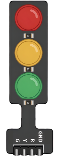
Pin Configuration and Descriptions

The pin configuration for a typical 3-LED traffic light module is as follows:

Pin Name Description
1 Red LED (+) Positive terminal for the red LED
2 Yellow LED (+) Positive terminal for the yellow LED
3 Green LED (+) Positive terminal for the green LED
4 GND (-) Common ground for all LEDs

Note: Some modules may have built-in resistors for current limiting, while others may require external resistors.

Usage Instructions

How to Use the Component in a Circuit

  1. Power Supply: Connect the GND pin of the traffic light module to the ground of your power source or microcontroller. Supply 5V or 12V (depending on the module) to the LED pins via a microcontroller or external switches.
  2. Control Signals: Use digital output pins from a microcontroller (e.g., Arduino) to control the LEDs. Each LED can be turned on or off by sending a HIGH or LOW signal to its respective pin.
  3. Resistors: If the module does not include built-in resistors, connect a 220Ω resistor in series with each LED pin to limit current and prevent damage.

Important Considerations and Best Practices

  • Voltage Compatibility: Ensure the module's operating voltage matches your power source or microcontroller.
  • Current Limiting: Always use appropriate resistors if not built into the module.
  • Heat Management: Avoid prolonged operation at maximum brightness to prevent overheating.
  • Polarity: Double-check connections to avoid reversing polarity, which can damage the LEDs.

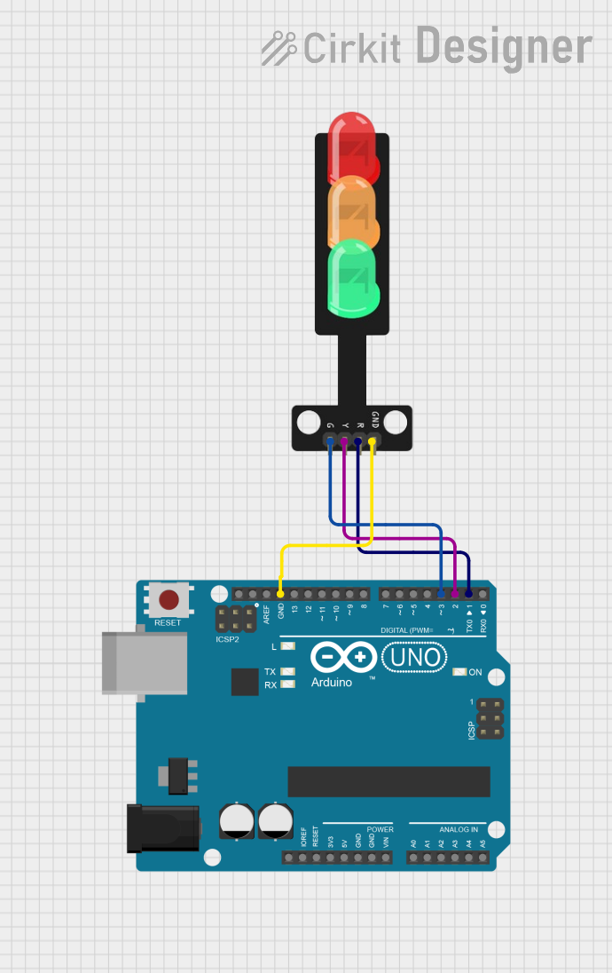
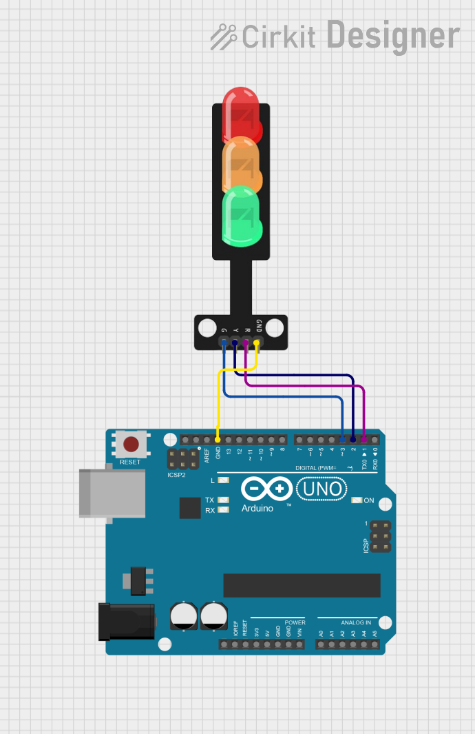
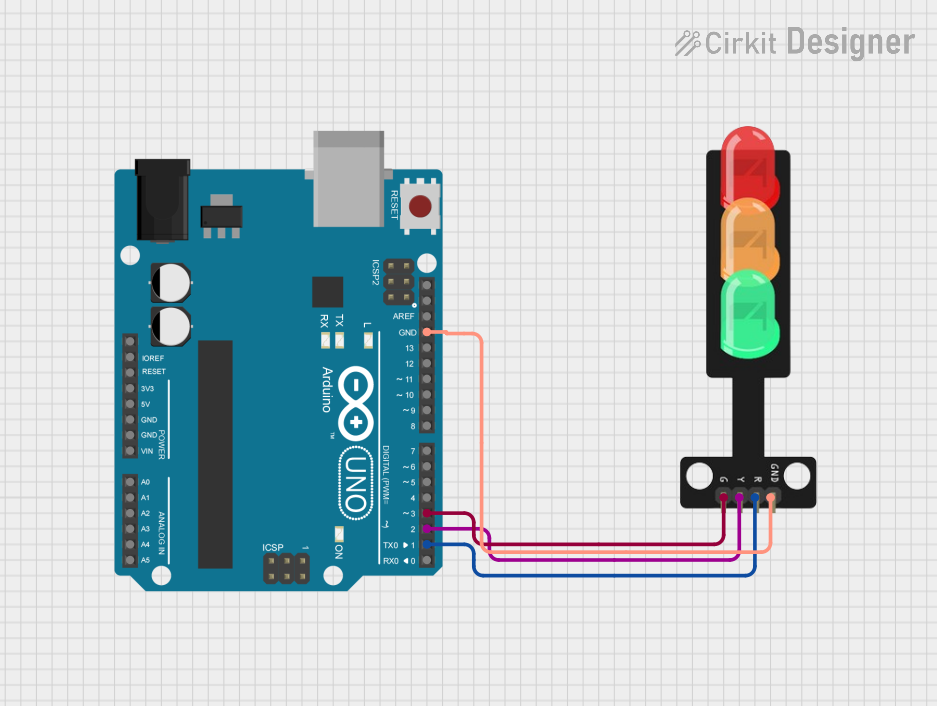
Example: Connecting to an Arduino UNO

Below is an example of how to connect and program a traffic light module with an Arduino UNO:

Circuit Connections

  • Connect the Red LED pin to Arduino digital pin 8.
  • Connect the Yellow LED pin to Arduino digital pin 9.
  • Connect the Green LED pin to Arduino digital pin 10.
  • Connect the GND pin of the module to the Arduino GND.

Arduino Code

// Traffic Light Simulation with Arduino UNO

// Define pin numbers for the LEDs
const int redLED = 8;    // Red LED connected to pin 8
const int yellowLED = 9; // Yellow LED connected to pin 9
const int greenLED = 10; // Green LED connected to pin 10

void setup() {
  // Set LED pins as output
  pinMode(redLED, OUTPUT);
  pinMode(yellowLED, OUTPUT);
  pinMode(greenLED, OUTPUT);
}

void loop() {
  // Red light ON for 5 seconds
  digitalWrite(redLED, HIGH);
  delay(5000); // Wait for 5 seconds
  digitalWrite(redLED, LOW);

  // Green light ON for 5 seconds
  digitalWrite(greenLED, HIGH);
  delay(5000); // Wait for 5 seconds
  digitalWrite(greenLED, LOW);

  // Yellow light ON for 2 seconds
  digitalWrite(yellowLED, HIGH);
  delay(2000); // Wait for 2 seconds
  digitalWrite(yellowLED, LOW);
}

Tip: Adjust the delay() values in the code to simulate different traffic light timings.

Troubleshooting and FAQs

Common Issues Users Might Face

  1. LEDs Not Lighting Up:

    • Check the power supply and ensure the module is receiving the correct voltage.
    • Verify that the GND pin is properly connected to the ground of the circuit.
    • Ensure resistors are used if required.
  2. Incorrect LED Behavior:

    • Double-check the pin connections between the module and the microcontroller.
    • Verify the code logic to ensure the correct sequence of LED activation.
  3. Overheating LEDs:

    • Ensure current-limiting resistors are in place if the module does not include them.
    • Avoid exceeding the recommended operating voltage.

Solutions and Tips for Troubleshooting

  • Use a multimeter to check voltage and continuity in the circuit.
  • Test each LED individually by connecting it directly to a power source with a resistor.
  • If using an Arduino, upload a simple blink sketch to test individual pins and connections.

FAQ:
Q: Can I use this module with a 3.3V microcontroller?
A: Yes, but the brightness of the LEDs may be reduced. Ensure the module is compatible with 3.3V logic levels.

Q: Do I need external resistors for this module?
A: It depends on the module. Check the datasheet or product description to confirm if resistors are built-in.

Q: Can I control the traffic light module with a Raspberry Pi?
A: Yes, you can use GPIO pins on the Raspberry Pi to control the LEDs, but ensure proper voltage levels and current limiting.

This concludes the documentation for the traffic light module.