How to Use Pixhawk Pro: Examples, Pinouts, and Specs
Introduction
The Pixhawk Pro is a versatile, open-source flight control hardware designed for drones and unmanned aerial vehicles (UAVs). It is equipped with advanced sensors, GPS integration, and supports a wide range of autopilot software, including PX4 and ArduPilot. This component is ideal for both hobbyists and professionals seeking reliable and precise control for their aerial systems.
Explore Projects Built with Pixhawk Pro
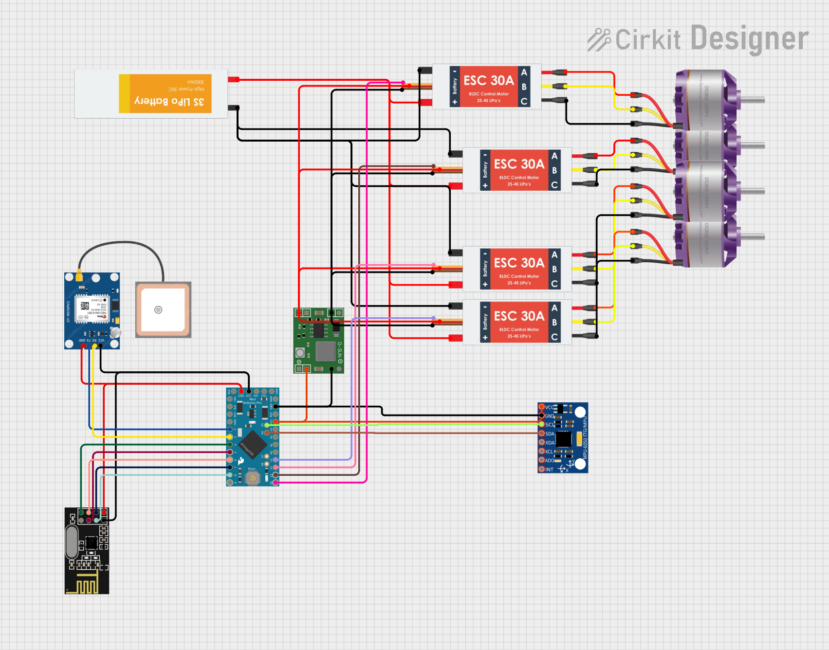

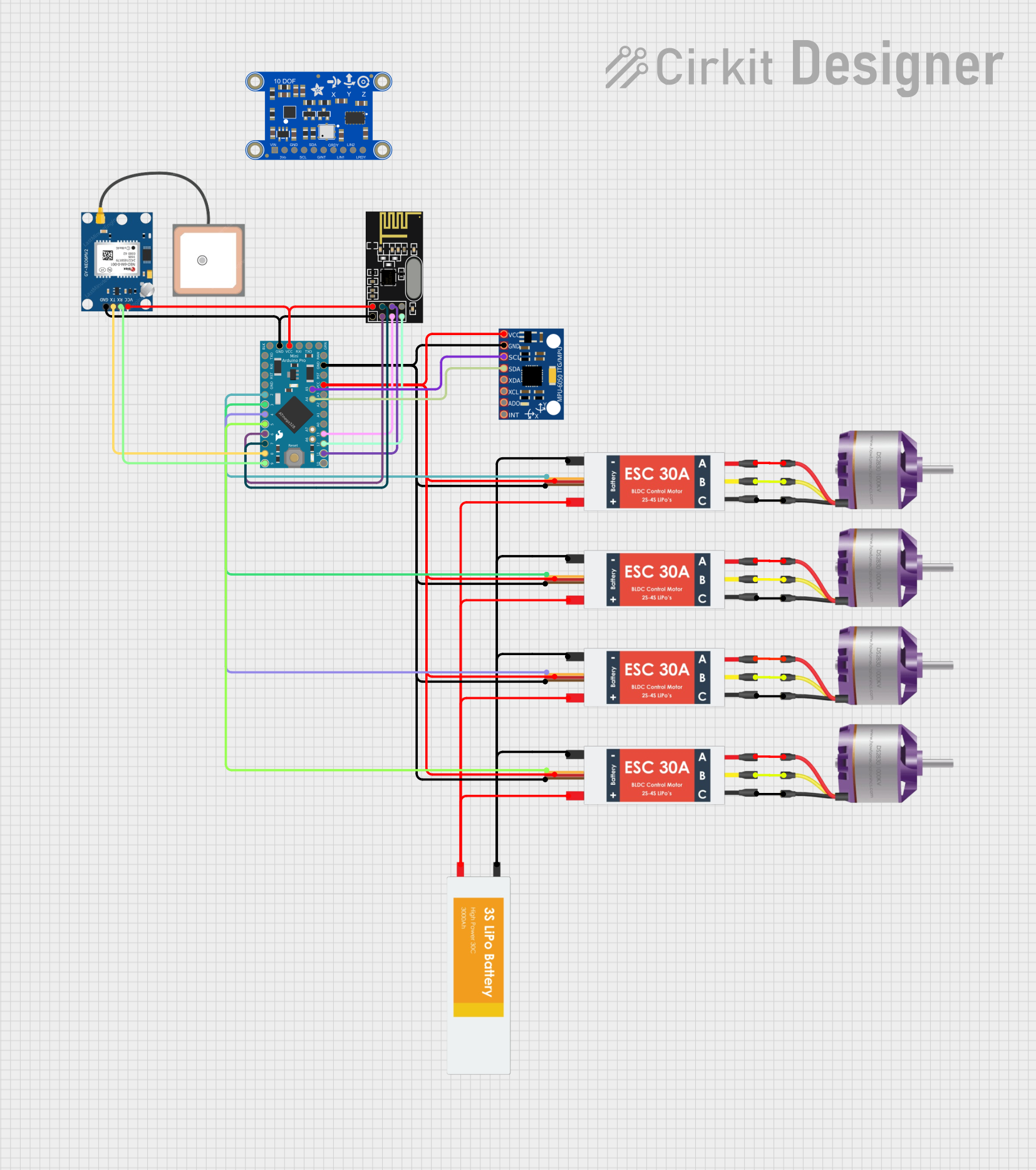

Explore Projects Built with Pixhawk Pro
Common Applications and Use Cases
- Autonomous drones for aerial photography and videography
- Industrial UAVs for surveying, mapping, and inspection
- Research and development in robotics and aviation
- Educational projects in flight control and autonomous systems
- Custom-built UAVs for racing or recreational purposes
Technical Specifications
The Pixhawk Pro is designed to deliver high performance and reliability. Below are its key technical details:
Key Technical Details
- Processor: STM32F7 series microcontroller with ARM Cortex-M7 core
- IMU Sensors: Triple redundant IMUs (accelerometers and gyroscopes)
- Barometer: High-precision barometer for altitude measurement
- GPS Support: External GPS module compatibility (e.g., u-blox M8N)
- Input Voltage: 4.1V to 5.7V
- Power Consumption: ~2.5W
- Communication Interfaces: UART, I2C, CAN, SPI, PWM, and ADC
- Dimensions: 50mm x 81.5mm x 15.5mm
- Weight: ~38g
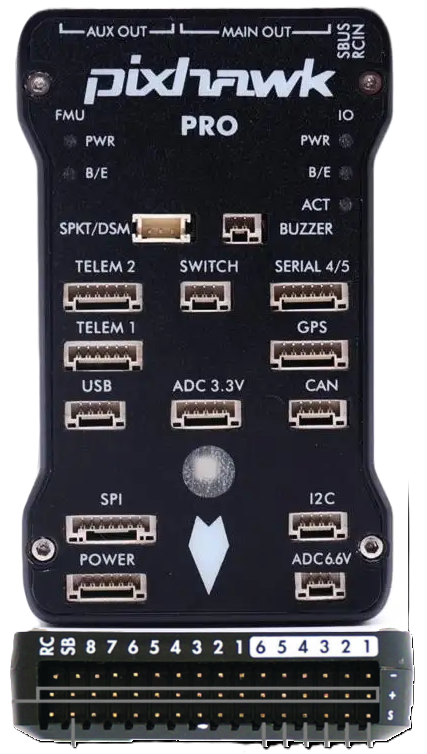
Pin Configuration and Descriptions
The Pixhawk Pro features multiple connectors for peripherals and sensors. Below is a summary of its pin configuration:
Power and Communication Ports
| Port Name | Pin | Description |
|---|---|---|
| Power Input | VCC | Main power input (4.1V to 5.7V) |
| GND | Ground connection | |
| UART1 | TX | Transmit data |
| RX | Receive data | |
| I2C | SCL | Clock line for I2C communication |
| SDA | Data line for I2C communication | |
| CAN | CAN_H | CAN bus high signal |
| CAN_L | CAN bus low signal |
PWM Outputs
| Pin | Description |
|---|---|
| PWM1 to PWM8 | Outputs for motor or servo control |
| GND | Ground connection for PWM signals |
Auxiliary Ports
| Port Name | Pin | Description |
|---|---|---|
| ADC | V_IN | Analog input for voltage measurement |
| GND | Ground connection | |
| GPS | TX | GPS transmit data |
| RX | GPS receive data | |
| GND | Ground connection |
Usage Instructions
The Pixhawk Pro is a powerful flight controller that requires proper setup and configuration to function optimally. Follow the steps below to integrate it into your UAV system:
Step 1: Powering the Pixhawk Pro
- Connect a regulated power source (4.1V to 5.7V) to the Power Input port.
- Ensure the power source can supply sufficient current for the Pixhawk Pro and connected peripherals.
Step 2: Connecting Peripherals
- Attach the GPS module to the GPS port for navigation and positioning.
- Connect motors or servos to the PWM outputs.
- Use the I2C or UART ports to connect additional sensors or communication modules.
Step 3: Configuring the Software
- Install compatible autopilot software such as PX4 or ArduPilot on the Pixhawk Pro.
- Use a ground control station (e.g., QGroundControl or Mission Planner) to configure flight parameters, calibrate sensors, and upload flight missions.
Step 4: Testing and Calibration
- Perform a pre-flight check to ensure all sensors and peripherals are functioning correctly.
- Calibrate the accelerometer, gyroscope, compass, and barometer using the ground control station software.
Arduino UNO Integration Example
While the Pixhawk Pro is typically used with dedicated autopilot software, it can communicate with an Arduino UNO for custom applications via UART. Below is an example code snippet for reading data from the Pixhawk Pro:
#include <SoftwareSerial.h>

// Define RX and TX pins for UART communication
#define RX_PIN 10
#define TX_PIN 11

// Create a SoftwareSerial object
SoftwareSerial pixhawkSerial(RX_PIN, TX_PIN);

void setup() {
  // Initialize serial communication with Pixhawk Pro
  pixhawkSerial.begin(57600); // Baud rate for Pixhawk communication
  Serial.begin(9600);         // Serial monitor for debugging

  Serial.println("Pixhawk Pro Communication Initialized");
}

void loop() {
  // Check if data is available from Pixhawk Pro
  if (pixhawkSerial.available()) {
    // Read and print data from Pixhawk Pro
    char data = pixhawkSerial.read();
    Serial.print("Received: ");
    Serial.println(data);
  }

  // Add a small delay to avoid overwhelming the serial buffer
  delay(10);
}
Important Considerations
- Use shielded cables for GPS and communication ports to minimize interference.
- Ensure proper vibration damping for the Pixhawk Pro to maintain sensor accuracy.
- Always perform a pre-flight check to verify system functionality.
Troubleshooting and FAQs
Common Issues and Solutions
Issue: Pixhawk Pro does not power on.
- Solution: Verify the power source voltage (4.1V to 5.7V) and check all connections.
Issue: GPS module not detected.
- Solution: Ensure the GPS module is connected to the correct port and powered. Check the baud rate settings in the ground control station.
Issue: Motors or servos not responding.
- Solution: Verify the PWM connections and ensure the motor/servo outputs are configured in the autopilot software.
Issue: Inconsistent altitude readings.
- Solution: Calibrate the barometer and ensure the Pixhawk Pro is mounted away from airflow disturbances.
FAQs
Q: Can the Pixhawk Pro be used with fixed-wing aircraft?
A: Yes, the Pixhawk Pro supports fixed-wing, multirotor, and VTOL configurations.Q: What is the maximum number of PWM outputs?
A: The Pixhawk Pro provides up to 8 PWM outputs for motor or servo control.Q: Is the Pixhawk Pro compatible with Raspberry Pi?
A: Yes, the Pixhawk Pro can communicate with a Raspberry Pi via UART or CAN interfaces.Q: How do I update the firmware?
A: Use a ground control station like QGroundControl to download and install the latest firmware.
By following this documentation, users can effectively integrate and operate the Pixhawk Pro in their UAV systems.