How to Use Arduino Nano: Examples, Pinouts, and Specs
Introduction
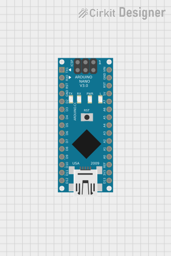
The Arduino Nano is a small, complete, and breadboard-friendly microcontroller board based on the ATmega328P. It offers the same functionality as the Arduino UNO but in a smaller form factor, making it ideal for projects with space constraints. The Nano is particularly popular among hobbyists and educators for its ease of use and versatility in various applications, including robotics, wearables, and IoT devices.
Explore Projects Built with Arduino Nano


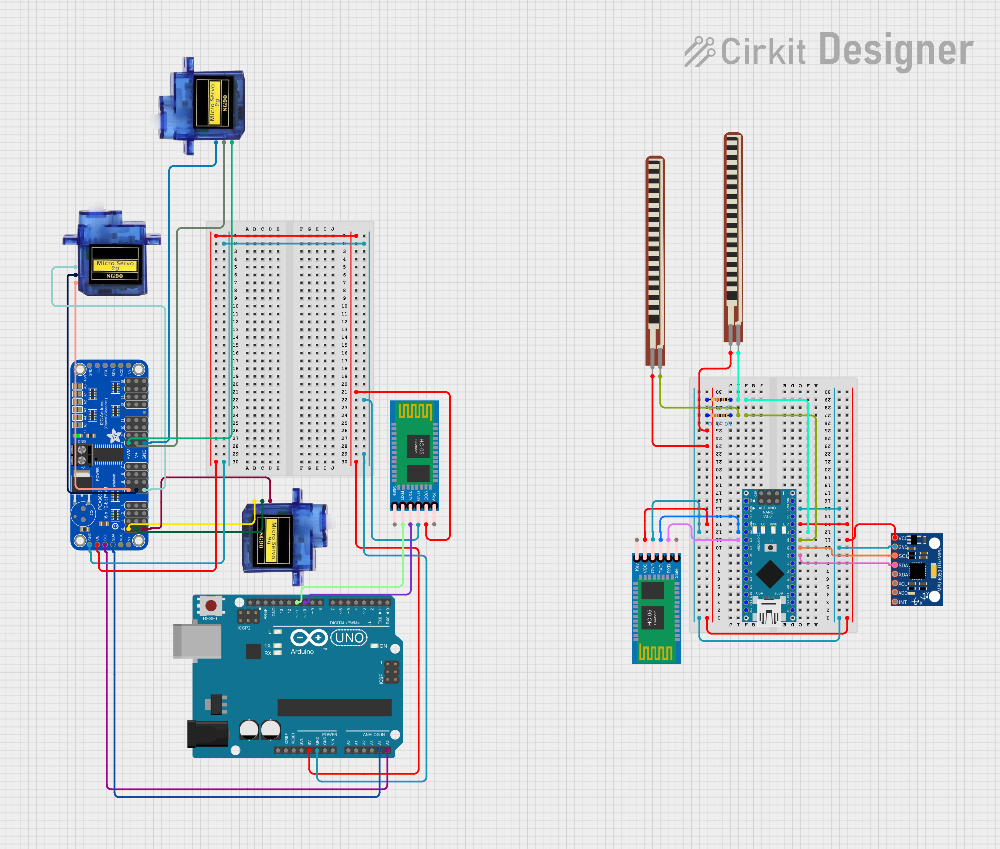
Explore Projects Built with Arduino Nano
Technical Specifications
Key Technical Details
- Microcontroller: ATmega328P
- Operating Voltage: 5V
- Input Voltage (recommended): 7-12V
- Input Voltage (limits): 6-20V
- Digital I/O Pins: 14 (of which 6 provide PWM output)
- Analog Input Pins: 8
- DC Current per I/O Pin: 40 mA
- DC Current for 3.3V Pin: 50 mA
- Flash Memory: 32 KB (ATmega328P) of which 2 KB used by bootloader
- SRAM: 2 KB (ATmega328P)
- EEPROM: 1 KB (ATmega328P)
- Clock Speed: 16 MHz
- LED_BUILTIN: Pin 13
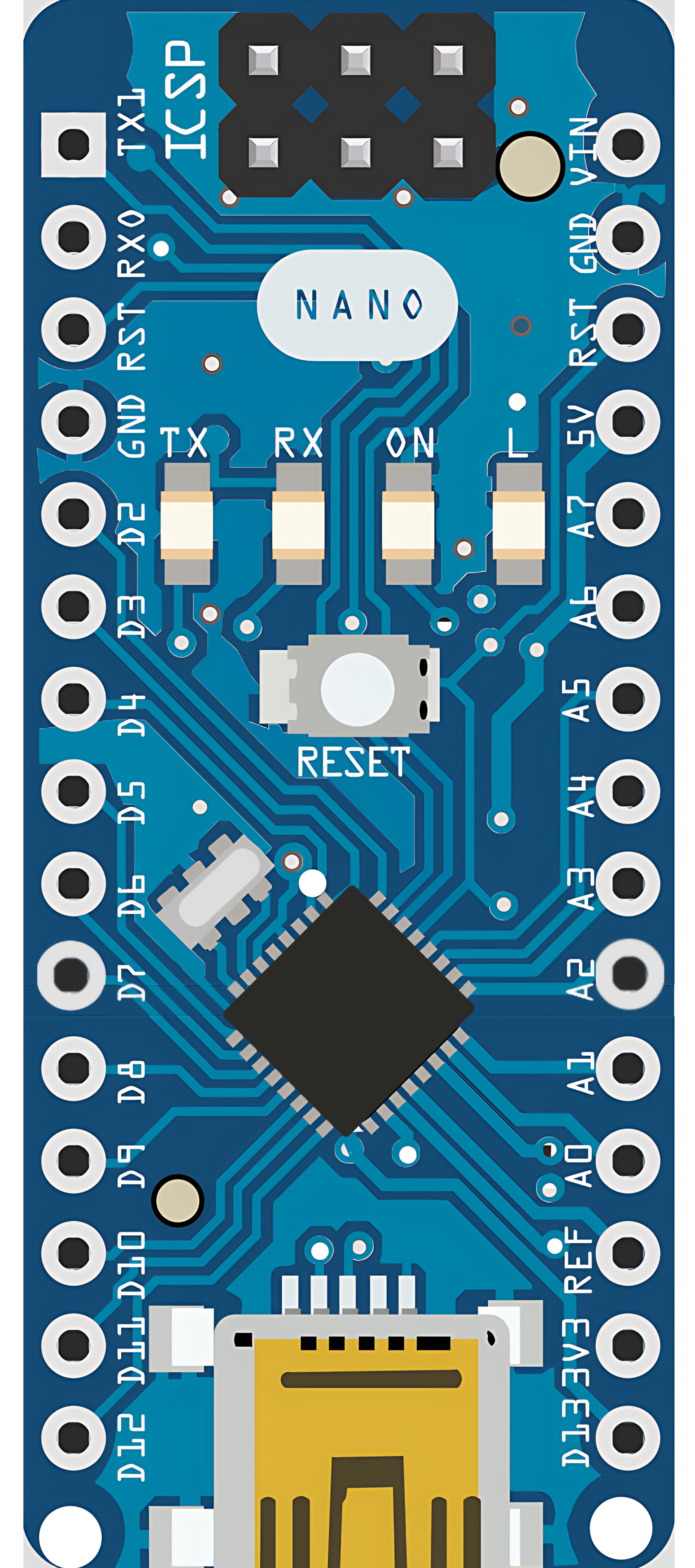
Pin Configuration and Descriptions
| Pin Number | Function | Description |
|---|---|---|
| 1 | RESET | Used to reset the microcontroller |
| 2-13 | Digital I/O | Digital input/output pins (PWM available on 3,5,6,9,10,11) |
| 14-21 | Analog In | Analog input pins |
| 22 | GND | Ground |
| 23 | AREF | Analog reference voltage for the ADC |
| 24 | 3V3 | 3.3V output from the onboard regulator |
| 25 | D13 LED | Connected to the built-in LED |
| 26 | +5V | Regulated 5V supply used to power the microcontroller |
| 27 | RST | Reset pin, can be used to externally reset the microcontroller |
| 28 | GND | Ground |
| 29 | VIN | Input voltage to the Arduino board |
| 30 | GND | Ground |
| 31 | TX (D1) | Transmit pin for serial communication |
| 32 | RX (D0) | Receive pin for serial communication |
Usage Instructions
Integrating with a Circuit
Powering the Board: The Arduino Nano can be powered via the Mini-B USB connection, 6-20V unregulated external power supply (pin 30), or 5V regulated external power supply (pin 26). The power source is automatically selected to the highest voltage source.
Connecting I/O Pins: Digital pins (2-13) can be used as input or output for interfacing with sensors, actuators, and other components. Analog pins (14-21) are primarily for input but can also serve as digital pins if needed.
Programming the Board: Connect the Nano to a computer using a Mini-B USB cable. Select 'Arduino Nano' as the board and the corresponding COM port in the Arduino IDE.
Best Practices
- Always disconnect the Nano from power sources before making or altering connections.
- Use a current limiting resistor when connecting LEDs to digital pins.
- Avoid supplying voltage higher than 5V to the I/O pins to prevent damage.
- Ensure that the total current through all I/O pins does not exceed 200 mA.
Example Code for Blinking LED
// The setup function runs once when you press reset or power the board
void setup() {
  // initialize digital pin LED_BUILTIN as an output.
  pinMode(LED_BUILTIN, OUTPUT);
}

// The loop function runs over and over again forever
void loop() {
  digitalWrite(LED_BUILTIN, HIGH);   // turn the LED on (HIGH is the voltage level)
  delay(1000);                       // wait for a second
  digitalWrite(LED_BUILTIN, LOW);    // turn the LED off by making the voltage LOW
  delay(1000);                       // wait for a second
}
Troubleshooting and FAQs
Common Issues
- Nano not recognized by computer: Ensure the Mini-B USB cable is properly connected and the driver is installed.
- Sketch not uploading: Check the selected board and port in the Arduino IDE. Ensure the correct bootloader is selected under Processor in the Tools menu.
- I/O pin not working: Verify the pin is not damaged and is configured correctly in the sketch.
Solutions and Tips
- Use external power supply when using components that draw more current than the USB can provide.
- If the Nano freezes, press the reset button on the board to restart the microcontroller.
- For analog reference voltage, use the AREF pin with
analogReference()in the sketch.
FAQs
Q: Can I use the Arduino Nano on a breadboard? A: Yes, the Nano is designed to fit on a standard breadboard with all pins accessible.
Q: What is the difference between VIN and 5V pins? A: VIN is the input voltage to the Arduino when using an external power source. The 5V pin is the regulated output used to power the microcontroller and other components.
Q: How do I know if my Nano is genuine? A: Genuine Nanos have the Arduino logo and are sold by authorized distributors. Look for quality markings and packaging.
Q: Can I use the Nano for a battery-powered project? A: Yes, the Nano can be powered by batteries, but consider the voltage requirements and power consumption for your application.