How to Use GY-30 BH1750FVI Digital Light Intensity Illumination Sensor: Examples, Pinouts, and Specs
Introduction
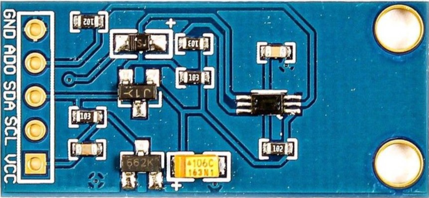
The GY-30 BH1750FVI is a digital ambient light sensor that provides an accurate measurement of illumination intensity through an I2C interface. This sensor is widely used in applications where light levels need to be measured, such as in smartphones, lighting control systems, and digital cameras to adjust brightness.
Explore Projects Built with GY-30 BH1750FVI Digital Light Intensity Illumination Sensor
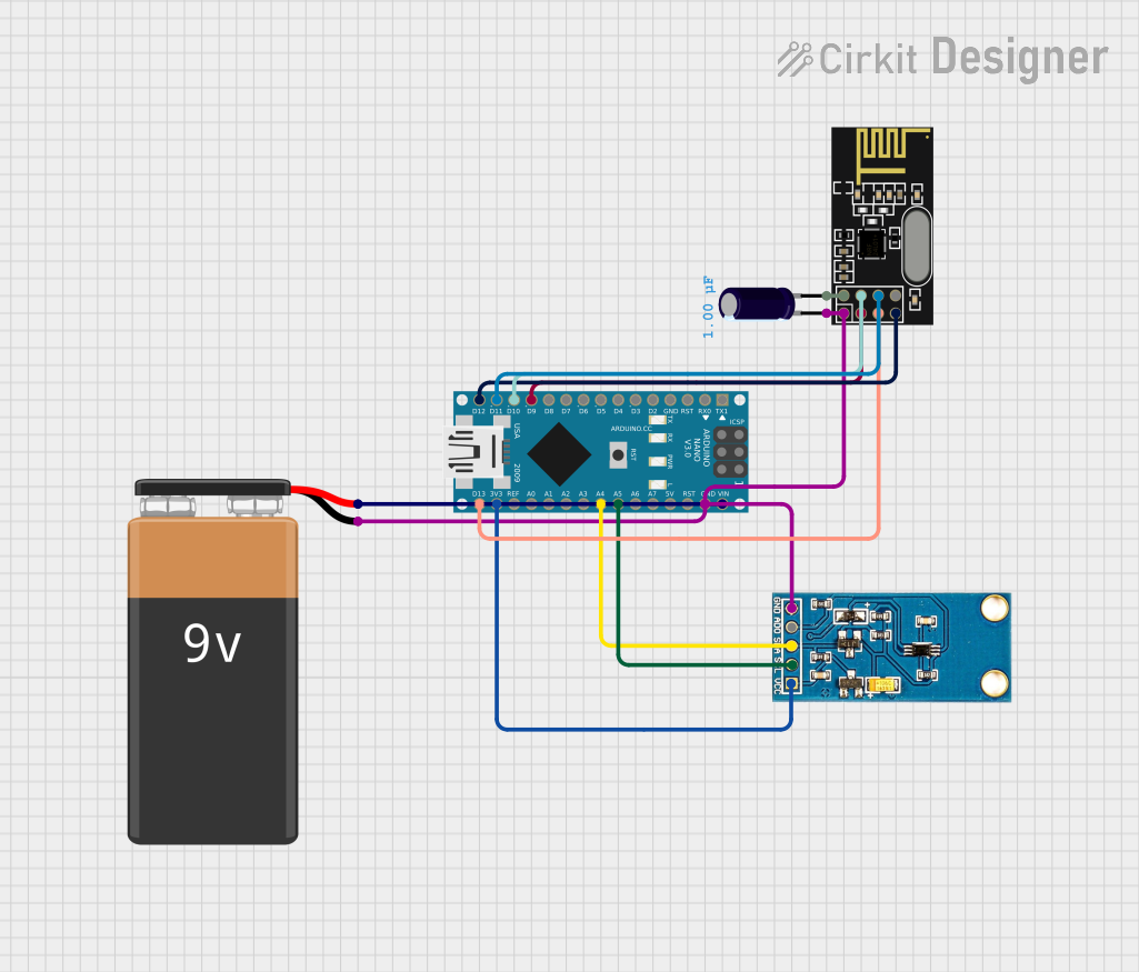
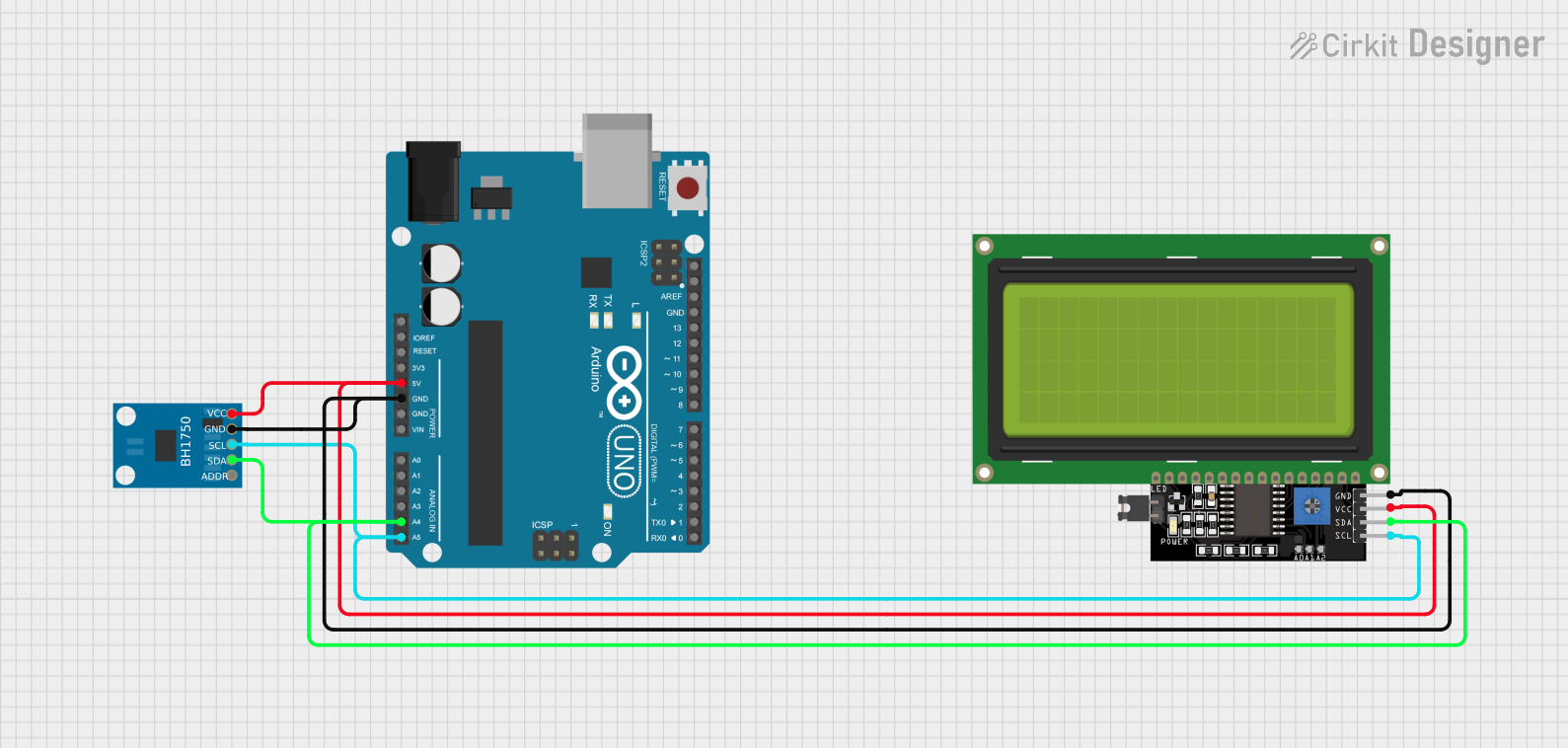
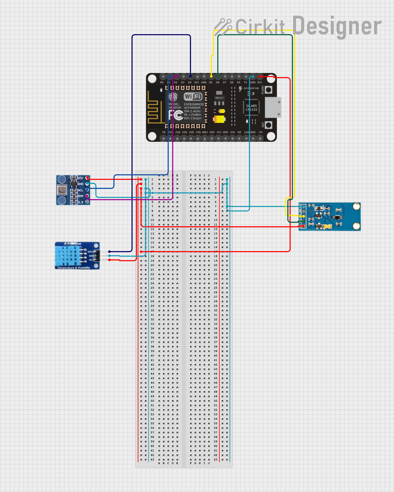
Explore Projects Built with GY-30 BH1750FVI Digital Light Intensity Illumination Sensor
Technical Specifications
Key Technical Details
- Supply Voltage (VCC): 2.4V to 3.6V
- Measurement Range: 1 - 65535 lux
- Spectral Responsibility: Close to human eye response
- I2C Bus Interface: Fast-mode (up to 400 kHz)
- Operating Temperature Range: -40°C to 85°C
- Resolution: 1 lux (High-Resolution Mode)
Pin Configuration and Descriptions
| Pin Number | Pin Name | Description |
|---|---|---|
| 1 | VCC | Power supply (2.4V to 3.6V) |
| 2 | GND | Ground |
| 3 | SCL | Serial Clock Line for I2C communication |
| 4 | SDA | Serial Data Line for I2C communication |
| 5 | ADDR | Address pin (floating, VCC or GND) |
Usage Instructions
Connecting to a Circuit
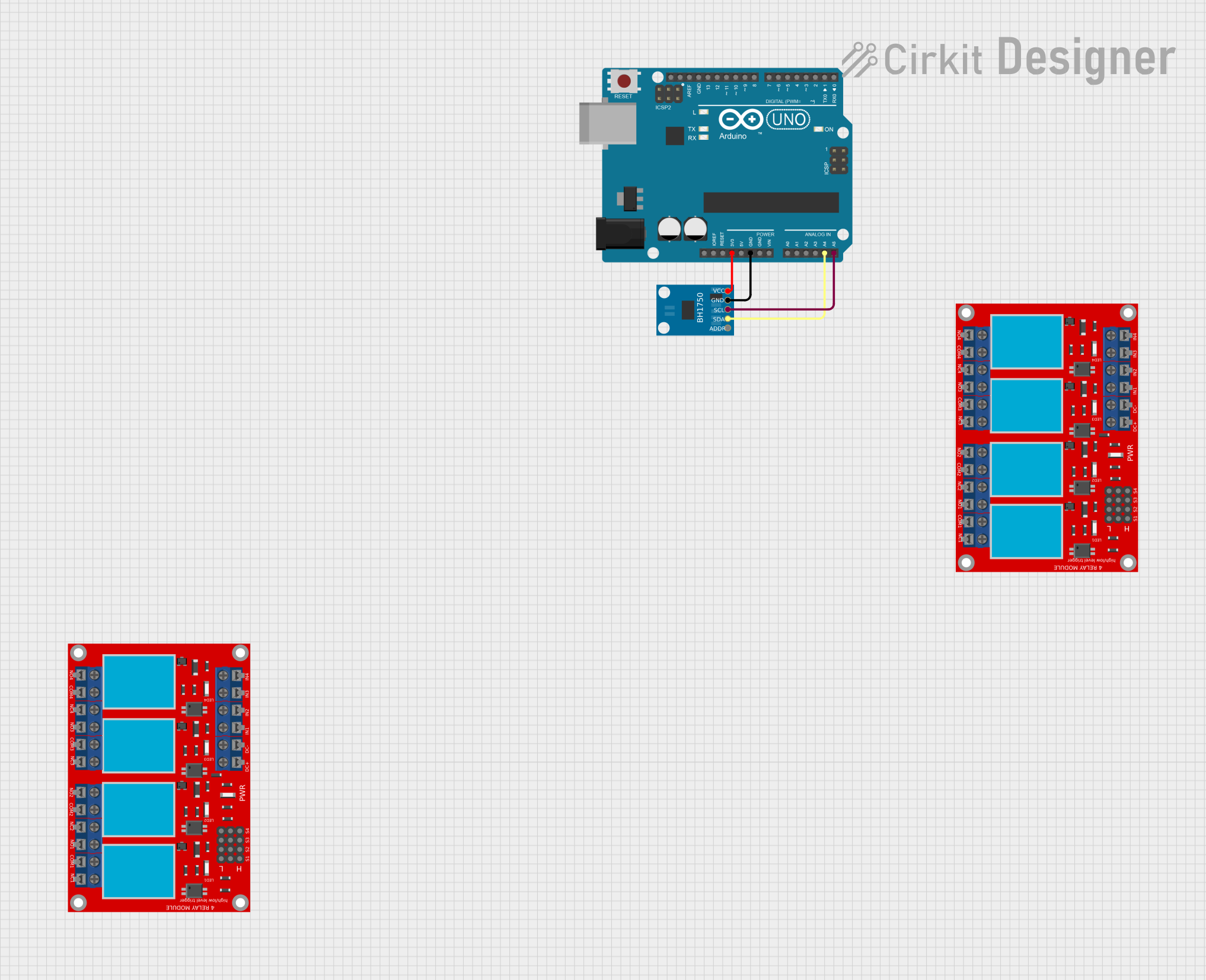
- Connect the VCC pin to a 3.3V supply from your microcontroller board (e.g., Arduino UNO).
- Connect the GND pin to the ground on your microcontroller board.
- Connect the SCL pin to the I2C clock pin on your microcontroller (A5 on Arduino UNO).
- Connect the SDA pin to the I2C data pin on your microcontroller (A4 on Arduino UNO).
- The ADDR pin can be left floating for the default address, connected to GND for address
0x23, or VCC for address0x5C.
Important Considerations and Best Practices
- Ensure that the power supply is within the specified range to prevent damage.
- Use pull-up resistors on the SCL and SDA lines if your microcontroller board does not have them built-in.
- Avoid exposing the sensor to direct sunlight or strong artificial light sources that could exceed its maximum range.
Sample Arduino Code
#include <Wire.h>
#include <BH1750.h>

BH1750 lightMeter;

void setup() {
  Wire.begin();
  Serial.begin(9600);
  lightMeter.begin(BH1750::CONTINUOUS_HIGH_RES_MODE);
  Serial.println(F("BH1750 Test"));
}

void loop() {
  float lux = lightMeter.readLightLevel();
  Serial.print("Light: ");
  Serial.print(lux);
  Serial.println(" lx");
  delay(1000);
}
Troubleshooting and FAQs
Common Issues
- Sensor Not Responding: Ensure that the I2C connections are correct and secure. Check that the correct I2C address is being used in your code.
- Inaccurate Readings: Make sure the sensor is not directly exposed to bright light sources and that it's within the operational temperature range.
Solutions and Tips for Troubleshooting
- If the sensor is not detected, scan the I2C bus with an I2C scanner sketch to confirm the device address.
- Use a logic analyzer or oscilloscope to check the integrity of the I2C signals if communication issues persist.
- Ensure that the microcontroller's logic level matches the sensor's voltage level to prevent communication issues.
FAQs
Q: Can the sensor be used with 5V systems? A: While the sensor operates at 2.4V to 3.6V, a level shifter is recommended for use with 5V systems.
Q: How can I change the I2C address of the sensor? A: The I2C address can be changed by connecting the ADDR pin to GND or VCC.
Q: Is it necessary to calibrate the sensor? A: The sensor comes pre-calibrated, but for precise applications, you may need to calibrate against a known light source.
Q: What is the maximum I2C speed supported by the sensor? A: The sensor supports I2C fast-mode, which can go up to 400 kHz.
Remember to always consult the sensor's datasheet for the most accurate and detailed information.