
How to Use HMC1052L: Examples, Pinouts, and Specs
 Design with HMC1052L in Cirkit Designer
Introduction
The HMC1052L is a high-performance RF mixer designed for use in various communication applications. It is engineered to deliver low conversion loss, high linearity, and wide bandwidth, making it an ideal choice for both upconversion and downconversion tasks in RF signal processing. This component is widely used in wireless communication systems, radar systems, and other RF-based applications where signal integrity and performance are critical.
Explore Projects Built with HMC1052L
 Open Project in Cirkit Designer
 Open Project in Cirkit Designer
 Open Project in Cirkit Designer
 Open Project in Cirkit Designer
Explore Projects Built with HMC1052L
Open Project in Cirkit DesignerOpen Project in Cirkit DesignerOpen Project in Cirkit DesignerOpen Project in Cirkit DesignerCommon Applications:
- Wireless communication systems (e.g., cellular networks, Wi-Fi)
- Radar and satellite communication systems
- Test and measurement equipment
- Signal processing in RF and microwave circuits
Technical Specifications
The HMC1052L is designed to meet the demanding requirements of RF signal processing. Below are its key technical specifications:
Key Specifications:
| Parameter | Value |
|---|---|
| Frequency Range | DC to 4 GHz |
| Conversion Loss | 7 dB typical |
| Input IP3 (Linearity) | +23 dBm typical |
| LO Drive Level | +13 dBm |
| RF Input Power Range | -10 dBm to +10 dBm |
| Isolation (LO to RF) | 40 dB typical |
| Operating Temperature | -40°C to +85°C |
| Package Type | Surface Mount (SMT) |
Pin Configuration and Descriptions:
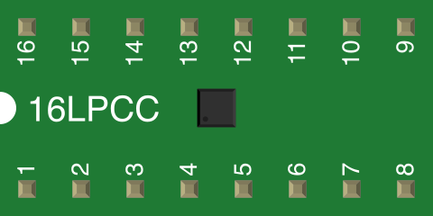
The HMC1052L is typically available in a surface-mount package with the following pin configuration:
| Pin Number | Pin Name | Description |
|---|---|---|
| 1 | RF | RF input signal (to be mixed) |
| 2 | GND | Ground connection |
| 3 | LO | Local oscillator input |
| 4 | GND | Ground connection |
| 5 | IF | Intermediate frequency (IF) output |
| 6 | GND | Ground connection |
Note: Ensure proper grounding for optimal performance and minimal noise interference.
Usage Instructions
The HMC1052L is straightforward to use in RF circuits, but proper design considerations are essential to achieve optimal performance.
How to Use the HMC1052L in a Circuit:
Power Supply and Grounding:
- Ensure a stable power supply and proper grounding to minimize noise.
- Use decoupling capacitors near the component to filter out high-frequency noise.
Connecting the RF Input (Pin 1):
- Connect the RF signal to the RF input pin. Use impedance-matched transmission lines (typically 50 ohms) to minimize signal loss.
Local Oscillator Input (Pin 3):
- Provide a stable LO signal with the recommended drive level of +13 dBm.
- Use a high-quality signal generator or oscillator for the LO input.
Intermediate Frequency Output (Pin 5):
- The mixed signal (IF output) will be available at this pin.
- Use appropriate filtering to isolate the desired frequency components.
Ground Connections (Pins 2, 4, 6):
- Connect all ground pins to a low-impedance ground plane for optimal performance.
Important Considerations:
- Impedance Matching: Ensure all input and output connections are impedance-matched to 50 ohms to minimize reflections and losses.
- Thermal Management: Operate the component within the specified temperature range (-40°C to +85°C). Use proper heat dissipation techniques if necessary.
- Signal Isolation: Maintain adequate isolation between the RF, LO, and IF paths to prevent signal leakage and interference.
Example Circuit:
Below is an example of how the HMC1052L can be used in a basic RF mixer circuit:
       +-------------------+
       |                   |
 RF -->| RF            IF  |--> Mixed Signal (IF Output)
       |                   |
 LO -->| LO                |
       |                   |
       +-------------------+
Note: This is a conceptual diagram. Refer to the manufacturer's datasheet for detailed PCB layout guidelines.
Troubleshooting and FAQs
Common Issues and Solutions:
Issue: High conversion loss or poor signal quality.
- Solution: Check impedance matching on all ports (RF, LO, IF). Ensure the LO drive level is within the recommended range (+13 dBm).
Issue: Signal leakage between LO and RF paths.
- Solution: Verify proper grounding and isolation between signal paths. Use high-quality RF components and shielding if necessary.
Issue: Excessive noise in the output signal.
- Solution: Ensure proper grounding and use decoupling capacitors to filter out noise. Verify the quality of the LO signal.
Issue: Component overheating.
- Solution: Operate the component within the specified temperature range. Use heat sinks or thermal vias on the PCB if needed.
FAQs:
Q1: Can the HMC1052L be used for frequencies above 4 GHz?
A1: No, the HMC1052L is designed for operation up to 4 GHz. For higher frequencies, consider using a different mixer with a wider frequency range.
Q2: What type of LO signal is required?
A2: The LO signal should be a stable sinusoidal waveform with a drive level of +13 dBm for optimal performance.
Q3: Is the HMC1052L suitable for both upconversion and downconversion?
A3: Yes, the HMC1052L can be used for both upconversion and downconversion tasks in RF signal processing.
Q4: How can I minimize signal reflections?
A4: Use impedance-matched transmission lines (50 ohms) and ensure proper PCB layout practices to minimize reflections.
By following the guidelines and recommendations in this documentation, users can effectively integrate the HMC1052L into their RF systems for reliable and high-performance signal processing.