How to Use 3P Breaker: Examples, Pinouts, and Specs
Introduction
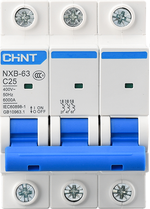
A 3P (three-pole) breaker is a type of circuit breaker designed to protect three-phase electrical circuits from overloads and short circuits. It interrupts the flow of electricity when it detects a fault, ensuring safety and preventing damage to electrical equipment.
Three-phase systems are commonly used in industrial and commercial settings due to their efficiency in transmitting power. The 3P breaker is an essential component in these systems, providing reliable protection and ensuring operational safety.
Explore Projects Built with 3P Breaker

Explore Projects Built with 3P Breaker
Common Applications and Use Cases
- Industrial machinery and equipment protection
- Commercial building power distribution systems
- Motor control centers (MCCs)
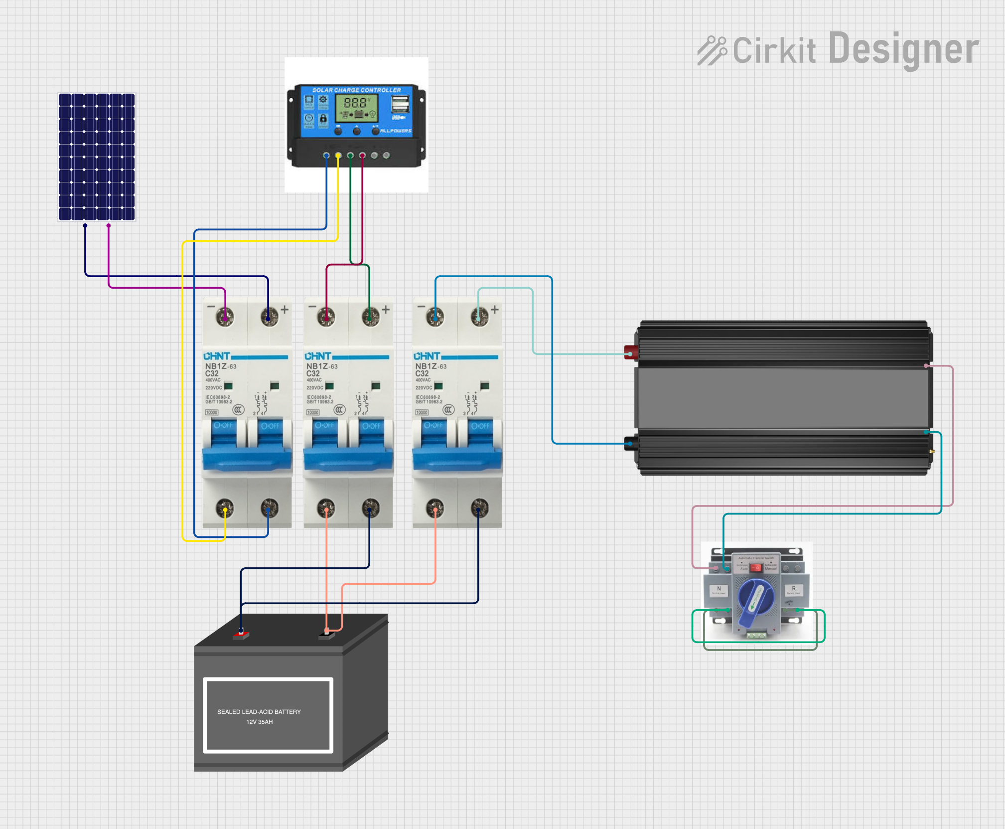
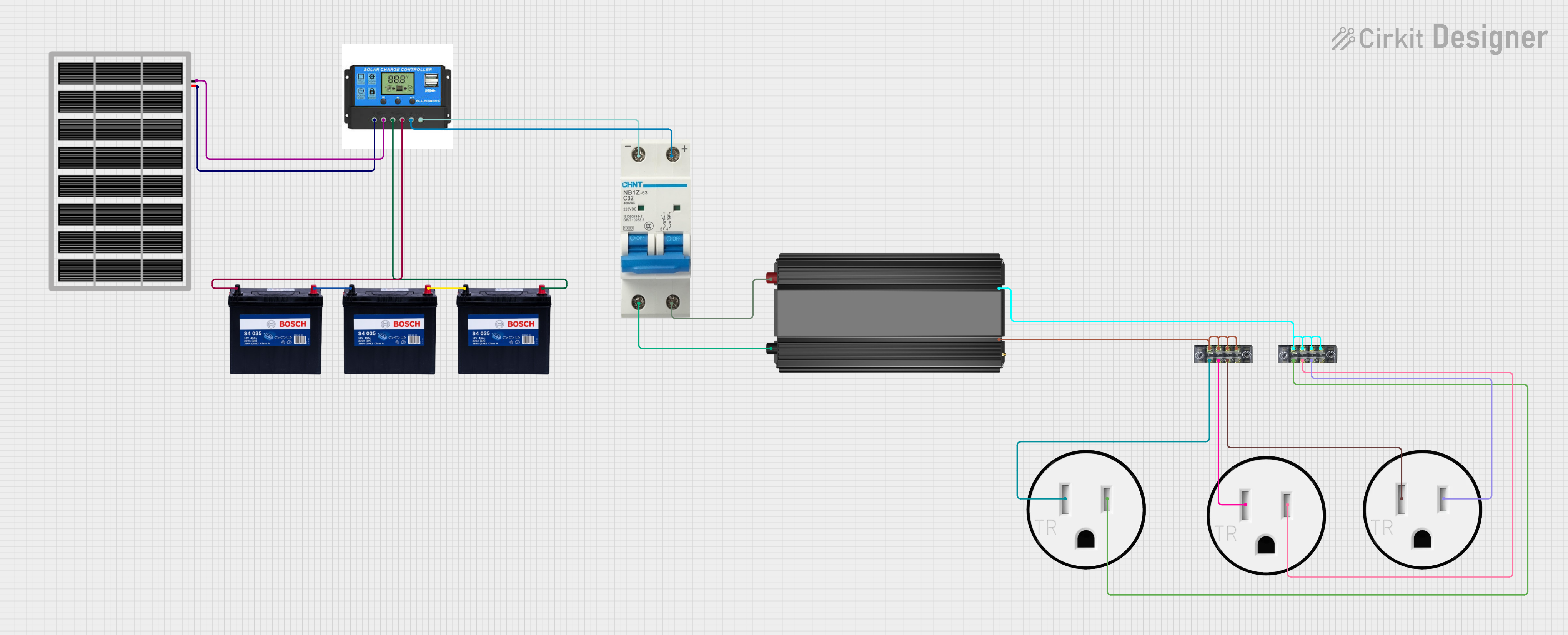
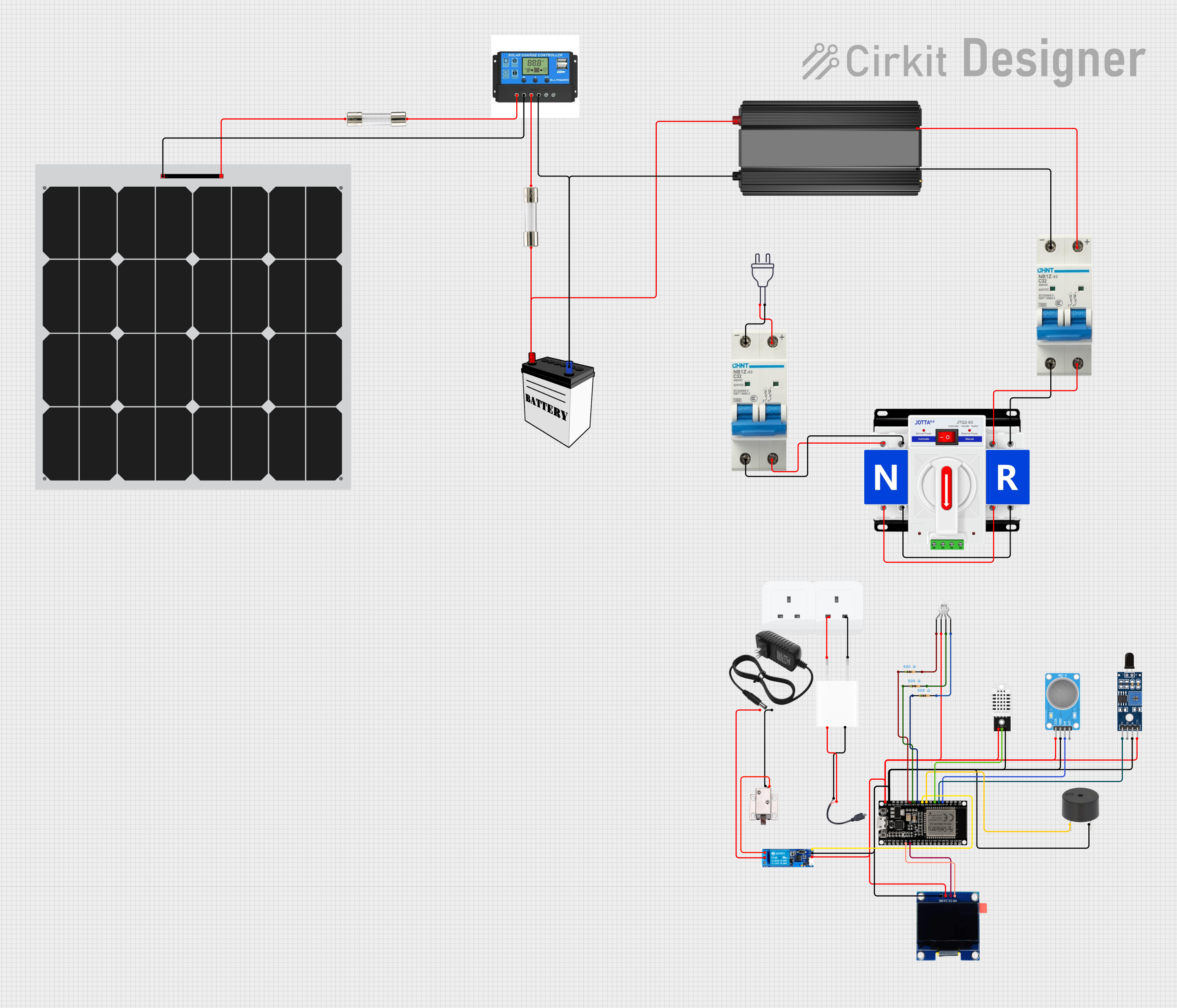
- Renewable energy systems (e.g., solar inverters, wind turbines)
- Data centers and server rooms
- HVAC systems
Technical Specifications
Below are the key technical details and pin configuration for a typical 3P breaker. Note that specifications may vary depending on the manufacturer and model.
Key Technical Details
| Parameter | Value/Range |
|---|---|
| Rated Voltage | 400V to 690V AC (typical) |
| Rated Current | 10A to 1600A (varies by model) |
| Breaking Capacity | 10kA to 100kA (depends on model) |
| Number of Poles | 3 |
| Frequency | 50Hz or 60Hz |
| Operating Temperature | -25°C to +70°C |
| Mounting Type | DIN rail or panel-mounted |
| Trip Mechanism | Thermal-magnetic or electronic |
Pin Configuration and Descriptions
The 3P breaker has three input terminals and three output terminals, corresponding to the three phases (L1, L2, L3) of the electrical system.
| Terminal Label | Description |
|---|---|
| L1 (Input) | Phase 1 input terminal |
| L2 (Input) | Phase 2 input terminal |
| L3 (Input) | Phase 3 input terminal |
| L1 (Output) | Phase 1 output terminal |
| L2 (Output) | Phase 2 output terminal |
| L3 (Output) | Phase 3 output terminal |
Usage Instructions
How to Use the 3P Breaker in a Circuit
- Determine the Specifications: Select a 3P breaker with the appropriate voltage, current, and breaking capacity for your application.
- Mount the Breaker: Install the breaker on a DIN rail or panel, ensuring it is securely fastened.
- Connect the Input Terminals: Connect the three-phase power supply to the input terminals (L1, L2, L3) of the breaker.
- Connect the Output Terminals: Connect the load (e.g., motor, equipment) to the output terminals (L1, L2, L3).
- Test the Circuit: Power on the system and verify that the breaker operates correctly. Test the trip mechanism by simulating an overload or short circuit if possible.
Important Considerations and Best Practices
- Select the Correct Breaker: Ensure the breaker’s rated current and voltage match the requirements of your system.
- Proper Wiring: Use appropriately rated cables for the connections to prevent overheating or voltage drops.
- Regular Maintenance: Periodically inspect the breaker for signs of wear, damage, or loose connections.
- Avoid Overloading: Do not exceed the breaker’s rated current to prevent nuisance tripping or damage.
- Environmental Conditions: Install the breaker in a clean, dry, and well-ventilated area to ensure optimal performance.
Example: Connecting a 3P Breaker to an Arduino-Controlled Motor
While a 3P breaker is not directly controlled by an Arduino, it can be used in conjunction with an Arduino-based motor control system. Below is an example of how an Arduino can control a three-phase motor, with the 3P breaker providing circuit protection.
/*
  Example: Arduino controlling a three-phase motor with a 3P breaker
  - The 3P breaker protects the motor from overloads and short circuits.
  - The Arduino controls a relay module to start/stop the motor.
*/

const int relayPin = 7; // Pin connected to the relay module

void setup() {
  pinMode(relayPin, OUTPUT); // Set relay pin as output
  digitalWrite(relayPin, LOW); // Ensure motor is off at startup
}

void loop() {
  // Example: Turn motor on for 5 seconds, then off for 5 seconds
  digitalWrite(relayPin, HIGH); // Turn motor on
  delay(5000); // Wait for 5 seconds
  digitalWrite(relayPin, LOW); // Turn motor off
  delay(5000); // Wait for 5 seconds
}
Note: The 3P breaker is connected between the power supply and the motor. The Arduino controls the motor indirectly via a relay or motor driver.
Troubleshooting and FAQs
Common Issues and Solutions
| Issue | Possible Cause | Solution |
|---|---|---|
| Breaker trips frequently | Overload or short circuit in the system | Check the load and wiring for faults |
| Breaker does not trip during faults | Faulty trip mechanism | Test and replace the breaker if needed |
| Overheating of breaker | Loose connections or undersized cables | Tighten connections, use proper cables |
| Difficulty in mounting | Incompatible mounting type | Verify compatibility with panel/DIN rail |
FAQs
Can a 3P breaker be used in single-phase systems?
- Yes, but only one pole will be used. It is generally not recommended as it is not cost-effective.
What is the difference between thermal-magnetic and electronic trip mechanisms?
- Thermal-magnetic breakers use a bimetallic strip and magnetic coil for tripping, while electronic breakers use sensors and microprocessors for precise protection.
How do I test if my 3P breaker is functioning correctly?
- Use a test button (if available) or simulate an overload/short circuit under controlled conditions to verify the trip mechanism.
Can I reset a tripped 3P breaker?
- Yes, after addressing the fault, switch the breaker to the "OFF" position and then back to "ON" to reset it.
By following this documentation, users can safely and effectively integrate a 3P breaker into their electrical systems.