How to Use DC-DC Step down converter 12V output: Examples, Pinouts, and Specs
Introduction
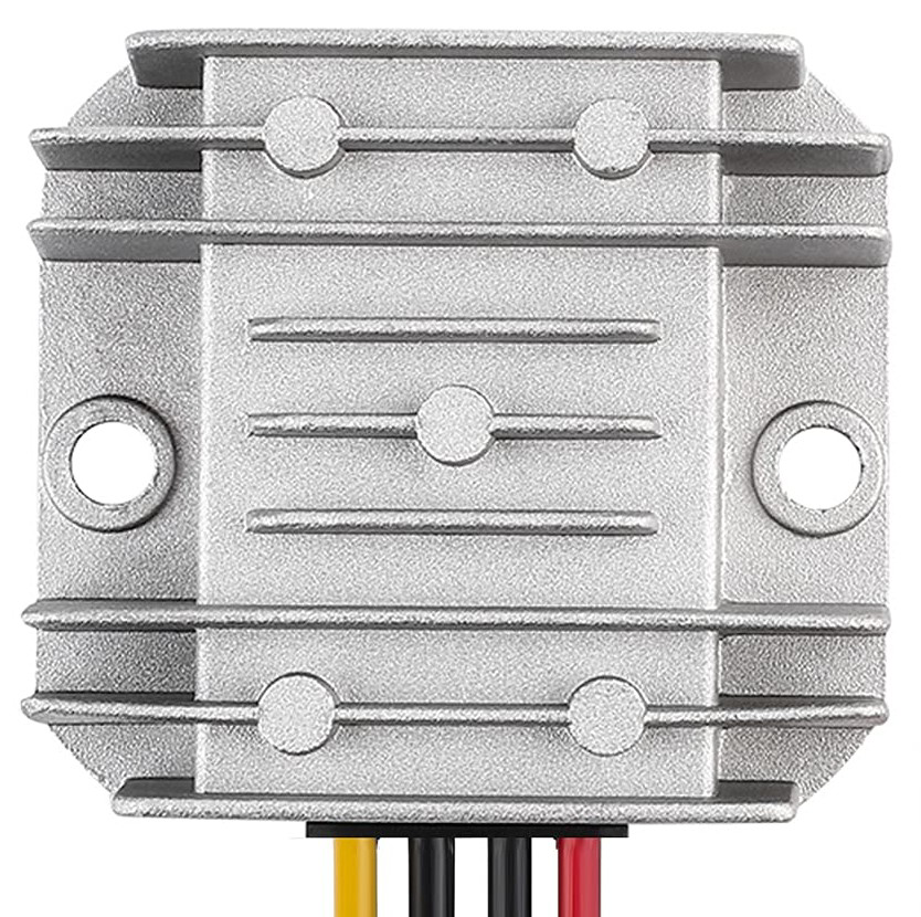
A DC-DC step down converter, also known as a buck converter, is a power electronics device that reduces a higher input voltage to a lower output voltage while maintaining high efficiency. This specific converter is designed to provide a stable 12V output from a higher voltage source, such as a 24V or 48V power supply.
Explore Projects Built with DC-DC Step down converter 12V output


Explore Projects Built with DC-DC Step down converter 12V output
Common Applications and Use Cases
- Powering 12V devices (e.g., fans, LED strips, and sensors) from higher voltage sources.
- Battery-powered systems where voltage regulation is required.
- Automotive applications to step down voltage from a car battery (e.g., 24V to 12V).
- Renewable energy systems, such as solar panels, to regulate output voltage.
- Industrial equipment requiring a stable 12V power supply.
Technical Specifications
Below are the key technical details for the DC-DC step down converter with a 12V output:
| Parameter | Value |
|---|---|
| Input Voltage Range | 15V to 40V |
| Output Voltage | 12V (fixed) |
| Output Current | Up to 5A (depending on input) |
| Efficiency | Up to 95% |
| Switching Frequency | 150 kHz |
| Operating Temperature | -40°C to +85°C |
| Protection Features | Overcurrent, Overtemperature, and Short Circuit Protection |
Pin Configuration and Descriptions
The DC-DC step down converter typically has the following pin configuration:
| Pin Name | Description |
|---|---|
| VIN+ | Positive input voltage terminal (connect to source) |
| VIN- | Negative input voltage terminal (connect to ground) |
| VOUT+ | Positive output voltage terminal (12V output) |
| VOUT- | Negative output voltage terminal (ground) |
Usage Instructions
How to Use the Component in a Circuit
Connect the Input Voltage:
- Connect the positive terminal of the input voltage source to the
VIN+pin. - Connect the negative terminal of the input voltage source to the
VIN-pin. - Ensure the input voltage is within the specified range (15V to 40V).
- Connect the positive terminal of the input voltage source to the
Connect the Output Load:
- Connect the positive terminal of the load to the
VOUT+pin. - Connect the negative terminal of the load to the
VOUT-pin.
- Connect the positive terminal of the load to the
Power On:
- Turn on the input voltage source. The converter will regulate the input voltage and provide a stable 12V output.
Verify Output:
- Use a multimeter to confirm the output voltage is 12V before connecting sensitive devices.
Important Considerations and Best Practices
- Input Voltage Range: Ensure the input voltage is always higher than 12V and within the specified range (15V to 40V). Exceeding the range may damage the converter.
- Heat Dissipation: For high current loads, the converter may generate heat. Use a heatsink or active cooling if necessary.
- Load Current: Do not exceed the maximum output current (5A). Overloading may trigger protection features or damage the device.
- Polarity: Double-check the polarity of the input and output connections to avoid damage.
- Filtering: For sensitive applications, consider adding input and output capacitors to reduce noise.
Example: Using the Converter with an Arduino UNO
The DC-DC step down converter can be used to power an Arduino UNO from a 24V source. Below is an example circuit and code:
Circuit Setup
- Connect the 24V source to the
VIN+andVIN-pins of the converter. - Connect the
VOUT+pin to the Arduino'sVINpin. - Connect the
VOUT-pin to the Arduino'sGNDpin.
Arduino Code Example
// Example code to blink an LED connected to pin 13 of the Arduino UNO
// Ensure the Arduino is powered via the DC-DC step down converter.

void setup() {
  pinMode(13, OUTPUT); // Set pin 13 as an output pin
}

void loop() {
  digitalWrite(13, HIGH); // Turn the LED on
  delay(1000);            // Wait for 1 second
  digitalWrite(13, LOW);  // Turn the LED off
  delay(1000);            // Wait for 1 second
}
Troubleshooting and FAQs
Common Issues and Solutions
No Output Voltage:
- Cause: Input voltage is below the minimum required (15V).
- Solution: Verify the input voltage and ensure it is within the specified range.
Overheating:
- Cause: High current load or insufficient cooling.
- Solution: Reduce the load current or add a heatsink/active cooling.
Output Voltage Not Stable:
- Cause: Insufficient input voltage or noisy power source.
- Solution: Use a stable input power source and consider adding input/output capacitors.
Short Circuit Protection Triggered:
- Cause: Output terminals are shorted.
- Solution: Disconnect the power, fix the short circuit, and reconnect.
FAQs
Q: Can I adjust the output voltage?
A: No, this converter provides a fixed 12V output. For adjustable output, use a variable DC-DC converter.Q: Can I use this converter with a 12V input?
A: No, the input voltage must be higher than 12V for proper operation.Q: Is the converter waterproof?
A: No, ensure the converter is used in a dry environment or enclosed in a waterproof case.Q: Can I connect multiple converters in parallel for higher current?
A: It is not recommended unless the converters are specifically designed for parallel operation.
This documentation provides all the necessary details to use the DC-DC step down converter effectively and troubleshoot common issues.