How to Use 1-5V to 5V 1A boost: Examples, Pinouts, and Specs
Documentation for 1-5V to 5V 1A Boost Converter
Manufacturer: Basement
1. Introduction
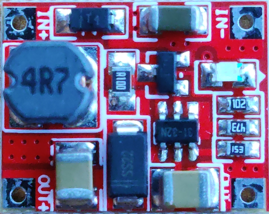
The 1-5V to 5V 1A Boost Converter is a compact and efficient DC-DC step-up module designed to convert a low input voltage (1-5V) into a stable 5V output. This module is ideal for applications requiring a consistent 5V power supply from low-voltage sources such as single-cell batteries, solar panels, or other low-voltage DC sources.
Common Applications
- Powering microcontrollers (e.g., Arduino, ESP32, Raspberry Pi Pico) from batteries.
- Portable electronics and battery-powered devices.
- Solar-powered systems.
- Emergency power supplies.
- DIY electronics projects requiring a stable 5V output.
2. Technical Specifications
The following table outlines the key technical details of the 1-5V to 5V 1A Boost Converter:
| Parameter | Value |
|---|---|
| Input Voltage Range | 1V to 5V |
| Output Voltage | 5V (regulated) |
| Maximum Output Current | 1A |
| Efficiency | Up to 90% (depending on load) |
| Dimensions | ~22mm x 17mm x 4mm |
| Operating Temperature | -40°C to +85°C |
Pin Configuration and Descriptions
| Pin Name | Description |
|---|---|
| VIN+ | Positive input voltage terminal (connect to the positive side of the power source). |
| VIN- | Negative input voltage terminal (connect to the ground of the power source). |
| VOUT+ | Positive output voltage terminal (provides a stable 5V output). |
| VOUT- | Negative output voltage terminal (common ground for the output). |
3. Usage Instructions
Connecting the Boost Converter
Input Connection:
- Connect the positive terminal of your power source (e.g., battery) to the
VIN+pin. - Connect the negative terminal of your power source to the
VIN-pin.
- Connect the positive terminal of your power source (e.g., battery) to the
Output Connection:
- Connect the
VOUT+pin to the positive terminal of your load (e.g., Arduino, sensor). - Connect the
VOUT-pin to the ground terminal of your load.
- Connect the
Power On:
- Ensure the input voltage is within the specified range (1-5V).
- The module will automatically boost the input voltage to a stable 5V output.
Important Considerations
- Input Voltage: Ensure the input voltage does not exceed 5V to prevent damage to the module.
- Load Current: Do not exceed the maximum output current of 1A to avoid overheating or failure.
- Heat Dissipation: For high-current applications, ensure proper ventilation or heat dissipation to maintain efficiency.
- Polarity: Double-check the polarity of your connections to avoid damaging the module.
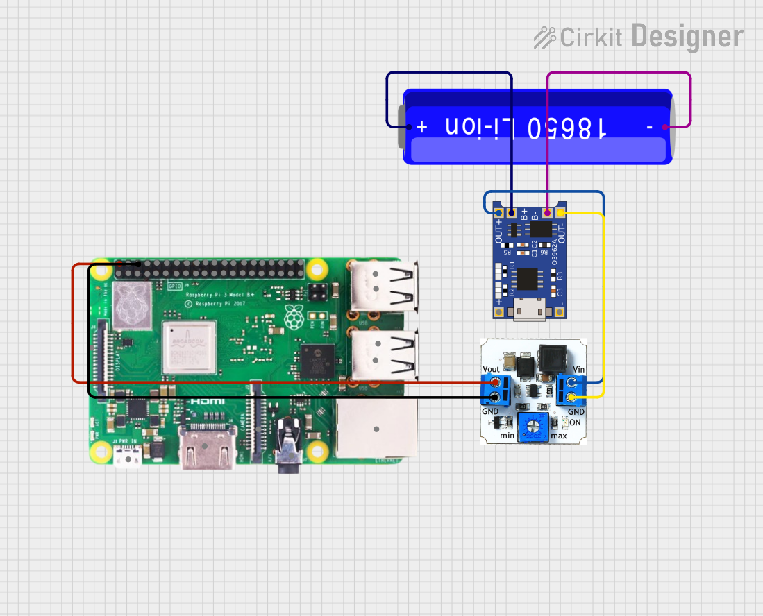
4. Example Application with Arduino UNO
The 1-5V to 5V Boost Converter can be used to power an Arduino UNO from a single AA battery (1.5V) or a 3.7V Li-ion battery. Below is an example circuit and code to demonstrate its use.
Circuit Diagram
- Connect the positive terminal of a 3.7V Li-ion battery to the
VIN+pin of the boost converter. - Connect the negative terminal of the battery to the
VIN-pin. - Connect the
VOUT+pin to the 5V pin of the Arduino UNO. - Connect the
VOUT-pin to the GND pin of the Arduino UNO.
Arduino Code Example
The following code blinks an LED connected to pin 13 of the Arduino UNO:
// Blink an LED connected to pin 13 of the Arduino UNO
// Ensure the Arduino is powered via the 1-5V to 5V Boost Converter

void setup() {
  pinMode(13, OUTPUT); // Set pin 13 as an output
}

void loop() {
  digitalWrite(13, HIGH); // Turn the LED on
  delay(1000);            // Wait for 1 second
  digitalWrite(13, LOW);  // Turn the LED off
  delay(1000);            // Wait for 1 second
}
5. Troubleshooting and FAQs
Common Issues and Solutions
| Issue | Possible Cause | Solution |
|---|---|---|
| No output voltage | Incorrect wiring or polarity | Double-check all connections and ensure correct polarity. |
| Output voltage is unstable | Input voltage is too low or fluctuating | Ensure the input voltage is within the 1-5V range and is stable. |
| Module overheats during operation | Excessive load current | Reduce the load current to below 1A or improve heat dissipation. |
| Arduino does not power on | Insufficient input voltage or current | Verify the input source can supply sufficient voltage and current. |
Frequently Asked Questions
Can I use this module with a solar panel?
Yes, as long as the solar panel provides an output voltage within the 1-5V range.What happens if the input voltage exceeds 5V?
Exceeding 5V may damage the module. Always ensure the input voltage is within the specified range.Can I use this module to charge a USB device?
Yes, but ensure the device's current requirements do not exceed 1A.Is the output voltage adjustable?
No, the output voltage is fixed at 5V.
This documentation provides a comprehensive guide to using the 1-5V to 5V 1A Boost Converter. For further assistance, refer to the manufacturer's support resources or contact Basement directly.
Explore Projects Built with 1-5V to 5V 1A boost


Explore Projects Built with 1-5V to 5V 1A boost