How to Use PT100 to RS485 Converter: Examples, Pinouts, and Specs
Introduction
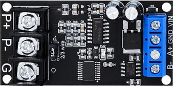
The PT100 to RS485 Converter is a specialized electronic device designed to convert the resistance signal from a PT100 temperature sensor into a digital RS485 signal. This conversion enables long-distance communication and seamless integration with digital systems such as PLCs, SCADA systems, and industrial automation equipment. The device ensures accurate temperature measurement and reliable data transmission, making it ideal for industrial, commercial, and laboratory applications.
Explore Projects Built with PT100 to RS485 Converter


Explore Projects Built with PT100 to RS485 Converter
Common Applications and Use Cases
- Industrial temperature monitoring and control
- HVAC systems for building automation
- Integration with PLCs and SCADA systems
- Long-distance temperature data transmission
- Laboratory and research equipment
Technical Specifications
Key Technical Details
| Parameter | Specification |
|---|---|
| Input Sensor Type | PT100 (Platinum Resistance Thermometer) |
| Input Range | -200°C to 850°C |
| Output Signal | RS485 (Modbus RTU Protocol) |
| Power Supply | 12V to 24V DC |
| Accuracy | ±0.1% of full scale |
| Communication Baud Rate | 9600 bps (default, configurable) |
| Operating Temperature Range | -40°C to 85°C |
| Dimensions | 75mm x 55mm x 25mm |
Pin Configuration and Descriptions
Input Side (PT100 Connection)
| Pin Number | Label | Description |
|---|---|---|
| 1 | PT+ | Positive terminal for PT100 sensor |
| 2 | PT- | Negative terminal for PT100 sensor |
Output Side (RS485 Connection)
| Pin Number | Label | Description |
|---|---|---|
| 1 | A | RS485 Data Line A |
| 2 | B | RS485 Data Line B |
| 3 | GND | Ground for RS485 communication |
Power Supply
| Pin Number | Label | Description |
|---|---|---|
| 1 | V+ | Positive terminal for DC power supply |
| 2 | V- | Negative terminal for DC power supply |
Usage Instructions
How to Use the Component in a Circuit
Connect the PT100 Sensor:
- Attach the PT100 sensor to the
PT+andPT-terminals on the input side of the converter. - Ensure proper wiring to avoid signal interference or incorrect readings.
- Attach the PT100 sensor to the
Connect the RS485 Output:
- Connect the
AandBterminals to the RS485 communication bus. - Use the
GNDterminal to establish a common ground with the receiving device.
- Connect the
Power the Converter:
- Supply a DC voltage (12V to 24V) to the
V+andV-terminals. - Verify the power supply polarity to prevent damage to the device.
- Supply a DC voltage (12V to 24V) to the
Configure Communication Settings:
- The default baud rate is 9600 bps. If needed, adjust the baud rate and other Modbus settings using the manufacturer's configuration software or DIP switches (if available).
Integrate with a Digital System:
- Use a compatible RS485-to-USB adapter or RS485 interface on your microcontroller/PLC to read the temperature data.
- Implement the Modbus RTU protocol to query the temperature values.
Important Considerations and Best Practices
- Use shielded cables for the PT100 sensor and RS485 communication to minimize noise and interference.
- Ensure proper termination resistors (typically 120Ω) are installed at both ends of the RS485 bus for reliable communication.
- Avoid running the PT100 and RS485 cables near high-power lines to prevent electromagnetic interference.
- Regularly calibrate the PT100 sensor and verify the converter's accuracy for critical applications.
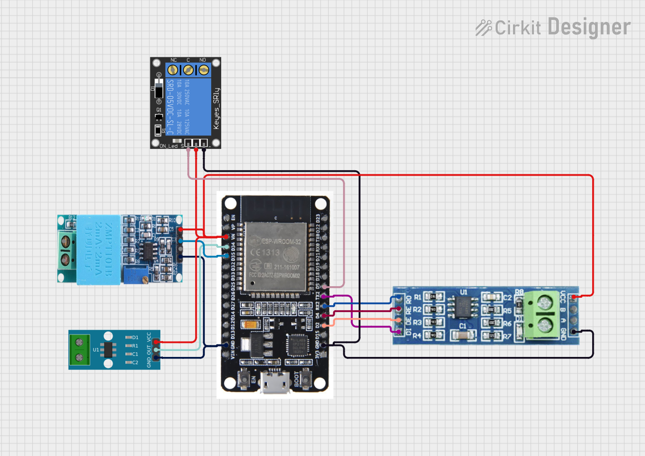
Example: Connecting to an Arduino UNO
To read temperature data from the PT100 to RS485 Converter using an Arduino UNO, you will need an RS485-to-TTL module. Below is an example code snippet:
#include <ModbusMaster.h>

// Create an instance of the ModbusMaster library
ModbusMaster node;

void setup() {
  Serial.begin(9600); // Initialize serial communication for debugging
  Serial.println("PT100 to RS485 Converter Example");

  // Initialize RS485 communication
  node.begin(1, Serial); // Set Modbus ID to 1 (default for the converter)
}

void loop() {
  uint8_t result;
  uint16_t temperature;

  // Read temperature data from holding register 0x0000
  result = node.readHoldingRegisters(0x0000, 1);

  if (result == node.ku8MBSuccess) {
    // Convert the raw data to temperature (example scaling factor: 0.1°C)
    temperature = node.getResponseBuffer(0);
    float tempC = temperature * 0.1; // Convert to Celsius
    Serial.print("Temperature: ");
    Serial.print(tempC);
    Serial.println(" °C");
  } else {
    Serial.println("Failed to read temperature data");
  }

  delay(1000); // Wait 1 second before the next read
}
Notes:
- Replace
0x0000with the actual register address for temperature data if it differs. - Ensure the Modbus ID and baud rate match the converter's configuration.
Troubleshooting and FAQs
Common Issues and Solutions
No Data Received on RS485 Bus:
- Verify the wiring of the
AandBterminals. Reversing these lines can cause communication failure. - Check the baud rate and Modbus ID settings on the converter and ensure they match the receiving device.
- Verify the wiring of the
Incorrect Temperature Readings:
- Ensure the PT100 sensor is properly connected and not damaged.
- Verify the scaling factor used in the software matches the converter's output format.
Intermittent Communication Failures:
- Check for proper termination resistors on the RS485 bus.
- Use shielded cables and avoid running communication lines near high-power equipment.
Device Not Powering On:
- Confirm the power supply voltage is within the specified range (12V to 24V DC).
- Check for loose or reversed power connections.
FAQs
Q: Can I use a PT1000 sensor with this converter?
A: No, this converter is specifically designed for PT100 sensors. Using a PT1000 sensor will result in incorrect readings.
Q: How long can the RS485 cable be?
A: RS485 communication supports cable lengths up to 1200 meters, but ensure proper termination and use of shielded cables for long distances.
Q: Can I connect multiple converters to the same RS485 bus?
A: Yes, RS485 supports multi-drop communication. Assign unique Modbus IDs to each converter to avoid conflicts.
Q: Is the converter compatible with 3-wire or 4-wire PT100 sensors?
A: This converter is typically designed for 2-wire PT100 sensors. For 3-wire or 4-wire sensors, consult the manufacturer's documentation for compatibility.