Cirkit Designer Logo
Cirkit Designer
Your all-in-one circuit design IDE
Home / 
Component Documentation

How to Use LED Matrix: Examples, Pinouts, and Specs

Image of LED Matrix
Cirkit Designer LogoDesign with LED Matrix in Cirkit Designer

Introduction

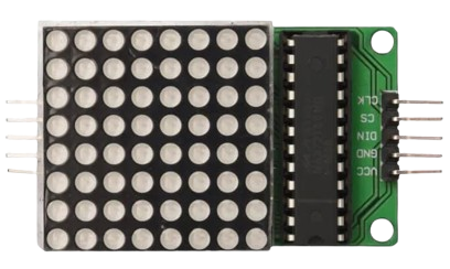
An LED matrix is a versatile electronic component that consists of a grid of LEDs arranged in rows and columns. It is commonly used in various applications such as digital clocks, advertising displays, and as a user interface for electronic devices. By controlling each LED individually, users can create patterns, text, and images for visual output.

Explore Projects Built with LED Matrix

Use Cirkit Designer to design, explore, and prototype these projects online. Some projects support real-time simulation. Click "Open Project" to start designing instantly!
ESP32-Controlled WS2812 LED Matrix Display with Resistor
Image of esp32 door sign project: A project utilizing LED Matrix in a practical application
This circuit features an ESP32 microcontroller connected to a 32x8 WS2812 LED matrix. The ESP32 controls the LED matrix through a 220-ohm resistor connected to its D12 pin, providing data input to the matrix, while power and ground connections are shared between the ESP32 and the LED matrix.
Cirkit Designer LogoOpen Project in Cirkit Designer
Arduino Nano Controlled LED Display and Relay System
Image of Design for Arduino Nano: A project utilizing LED Matrix in a practical application
This circuit features an Arduino Nano microcontroller connected to an 8x8 LED matrix and multiple individual LEDs with current-limiting resistors. The Arduino controls the LED matrix and individual LEDs, likely for display or signaling purposes. Additionally, there is a 1-channel relay module that can be controlled by the Arduino to switch external loads, and a USB connection for power and potential programming of the Arduino.
Cirkit Designer LogoOpen Project in Cirkit Designer
ESP32-Based Ambient Light Monitoring System with I2C LCD Display and Keypad Interface
Image of ESP roos: A project utilizing LED Matrix in a practical application
This circuit features an ESP32 microcontroller connected to an ambient light sensor, a 4x4 membrane matrix keypad, an I2C LCD screen, and a KY-008 laser emitter. The ESP32 reads ambient light intensity and displays it on the LCD screen, while the keypad allows user interaction to retrieve stored light intensity values from memory. The laser emitter is included in the circuit but not interfaced with the ESP32 in the provided code.
Cirkit Designer LogoOpen Project in Cirkit Designer
Arduino UNO Controlled LED Matrix and LCD Interface with Joystick Interaction
Image of Digital Game Circuit: A project utilizing LED Matrix in a practical application
This circuit features an Arduino UNO microcontroller interfaced with an 8x8 LED matrix, an LCD screen, and a KY-023 Dual Axis Joystick Module. The Arduino controls the LED matrix via digital pins D10-D12 and powers the matrix, LCD, and joystick module from its 5V output. The joystick's analog outputs are connected to the Arduino's analog inputs A0 and A1 for position sensing, while the LCD is controlled through digital pins D2-D6 and D13 for display purposes.
Cirkit Designer LogoOpen Project in Cirkit Designer

Explore Projects Built with LED Matrix

Use Cirkit Designer to design, explore, and prototype these projects online. Some projects support real-time simulation. Click "Open Project" to start designing instantly!
Image of esp32 door sign project: A project utilizing LED Matrix in a practical application
ESP32-Controlled WS2812 LED Matrix Display with Resistor
This circuit features an ESP32 microcontroller connected to a 32x8 WS2812 LED matrix. The ESP32 controls the LED matrix through a 220-ohm resistor connected to its D12 pin, providing data input to the matrix, while power and ground connections are shared between the ESP32 and the LED matrix.
Cirkit Designer LogoOpen Project in Cirkit Designer
Image of Design for Arduino Nano: A project utilizing LED Matrix in a practical application
Arduino Nano Controlled LED Display and Relay System
This circuit features an Arduino Nano microcontroller connected to an 8x8 LED matrix and multiple individual LEDs with current-limiting resistors. The Arduino controls the LED matrix and individual LEDs, likely for display or signaling purposes. Additionally, there is a 1-channel relay module that can be controlled by the Arduino to switch external loads, and a USB connection for power and potential programming of the Arduino.
Cirkit Designer LogoOpen Project in Cirkit Designer
Image of ESP roos: A project utilizing LED Matrix in a practical application
ESP32-Based Ambient Light Monitoring System with I2C LCD Display and Keypad Interface
This circuit features an ESP32 microcontroller connected to an ambient light sensor, a 4x4 membrane matrix keypad, an I2C LCD screen, and a KY-008 laser emitter. The ESP32 reads ambient light intensity and displays it on the LCD screen, while the keypad allows user interaction to retrieve stored light intensity values from memory. The laser emitter is included in the circuit but not interfaced with the ESP32 in the provided code.
Cirkit Designer LogoOpen Project in Cirkit Designer
Image of Digital Game Circuit: A project utilizing LED Matrix in a practical application
Arduino UNO Controlled LED Matrix and LCD Interface with Joystick Interaction
This circuit features an Arduino UNO microcontroller interfaced with an 8x8 LED matrix, an LCD screen, and a KY-023 Dual Axis Joystick Module. The Arduino controls the LED matrix via digital pins D10-D12 and powers the matrix, LCD, and joystick module from its 5V output. The joystick's analog outputs are connected to the Arduino's analog inputs A0 and A1 for position sensing, while the LCD is controlled through digital pins D2-D6 and D13 for display purposes.
Cirkit Designer LogoOpen Project in Cirkit Designer

Technical Specifications

General Characteristics

  • Manufacturer: Test
  • Part ID: Test
  • Display Type: LED Matrix
  • LED Color: (Typically red, green, blue, or white; specify if known)
  • Operating Voltage: (Typically 3.3V to 5V; specify if known)
  • Maximum Current per LED: (Specify if known)
  • Matrix Configuration: (e.g., 8x8, 16x16; specify if known)

Pin Configuration and Descriptions

Pin Number Name Description
1 VCC Connect to the power supply (3.3V to 5V)
2 GND Connect to the ground of the power supply
3 DIN Data input pin for sending LED data to the matrix
4 CS Chip select, used to enable and disable the matrix
5 CLK Clock pin, used to synchronize data transmission

Note: The actual pin configuration may vary depending on the specific LED matrix model. Refer to the manufacturer's datasheet for exact details.

Usage Instructions

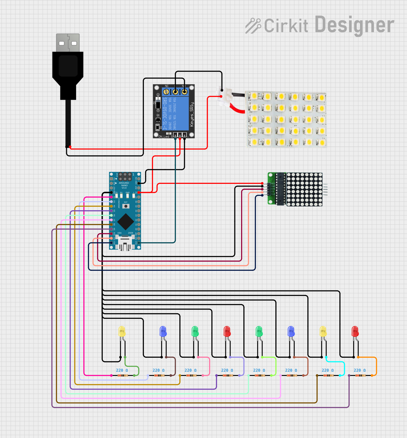
Connecting to a Circuit

  1. Power Supply: Connect the VCC pin to a suitable power supply (3.3V to 5V) and the GND pin to the ground.
  2. Data Input: Connect the DIN pin to the microcontroller's data output pin.
  3. Chip Select: The CS pin is used to select the LED matrix when multiple devices are connected to the same microcontroller.
  4. Clock: Connect the CLK pin to the microcontroller's clock output pin.

Best Practices

  • Use current-limiting resistors to prevent damage to the LEDs.
  • Avoid exceeding the maximum voltage and current ratings.
  • Implement proper heat dissipation techniques if the matrix is used at high brightness levels for extended periods.
  • Use a microcontroller with sufficient memory and processing power to handle the LED matrix's data requirements.

Example Code for Arduino UNO

#include <LedControl.h> // Include the LedControl library

// Pin configuration for the LED matrix
int DIN_PIN = 7;
int CS_PIN = 6;
int CLK_PIN = 5;

// Create a new LedControl object
LedControl lc = LedControl(DIN_PIN, CLK_PIN, CS_PIN, 1);

void setup() {
  // Initialize the LED matrix
  lc.shutdown(0, false);       // Wake up the display
  lc.setIntensity(0, 8);       // Set brightness level (0 is min, 15 is max)
  lc.clearDisplay(0);          // Clear display register
}

void loop() {
  // Display a simple pattern on the LED matrix
  for (int row = 0; row < 8; row++) {
    for (int col = 0; col < 8; col++) {
      lc.setLed(0, row, col, true);  // Turn on LED at (row, col)
      delay(200);
      lc.setLed(0, row, col, false); // Turn off LED at (row, col)
    }
  }
}

Note: The LedControl library is used for controlling LED matrices with Arduino. Make sure to install it using the Arduino Library Manager before compiling the code.

Troubleshooting and FAQs

Common Issues

  • LEDs Not Lighting Up: Ensure that the power supply is correctly connected and within the specified voltage range. Check the wiring of DIN, CS, and CLK pins.
  • Flickering Display: This may be due to insufficient power supply or loose connections. Verify the power source and secure all connections.
  • Incorrect Display Patterns: Double-check the code for any logical errors. Ensure that the correct pins are defined and that the library is properly included.

FAQs

Q: Can I control each LED individually? A: Yes, each LED can be controlled individually to display various patterns and characters.

Q: How do I connect multiple LED matrices? A: Multiple LED matrices can be daisy-chained by connecting the output pins of one matrix to the input pins of the next. Adjust the software accordingly to manage multiple devices.

Q: What is the maximum number of LED matrices I can control with an Arduino? A: The number is limited by the number of available pins and memory on the Arduino. Using shift registers or LED drivers can help control more matrices efficiently.

Q: Can I use a different microcontroller instead of an Arduino? A: Yes, any microcontroller with sufficient digital I/O pins can be used to control an LED matrix, provided you have the appropriate library or write your own control code.

For further assistance, please refer to the manufacturer's datasheet and technical support resources.