Cirkit Designer
Your all-in-one circuit design IDE
Home /
Component Documentation
How to Use Nextion: Examples, Pinouts, and Specs

 Design with Nextion in Cirkit Designer
Introduction
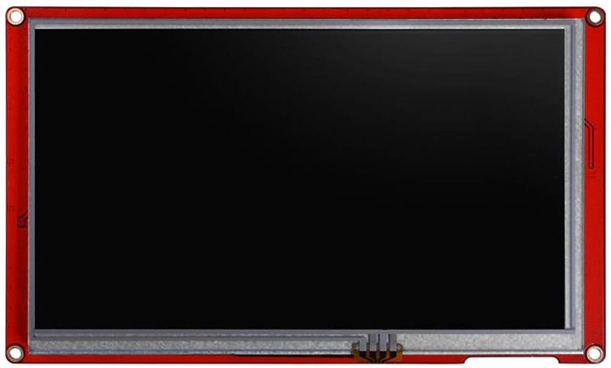
The Nextion 5-Inch HMI Display is a Human Machine Interface (HMI) solution that provides a control and visualization interface between a human and a process, machine, application, or appliance. Manufactured by Nextion, this display is widely used in embedded systems and IoT projects due to its ease of use and powerful features. It simplifies the interface design process, allowing developers to create complex interfaces without extensive coding.
Explore Projects Built with Nextion
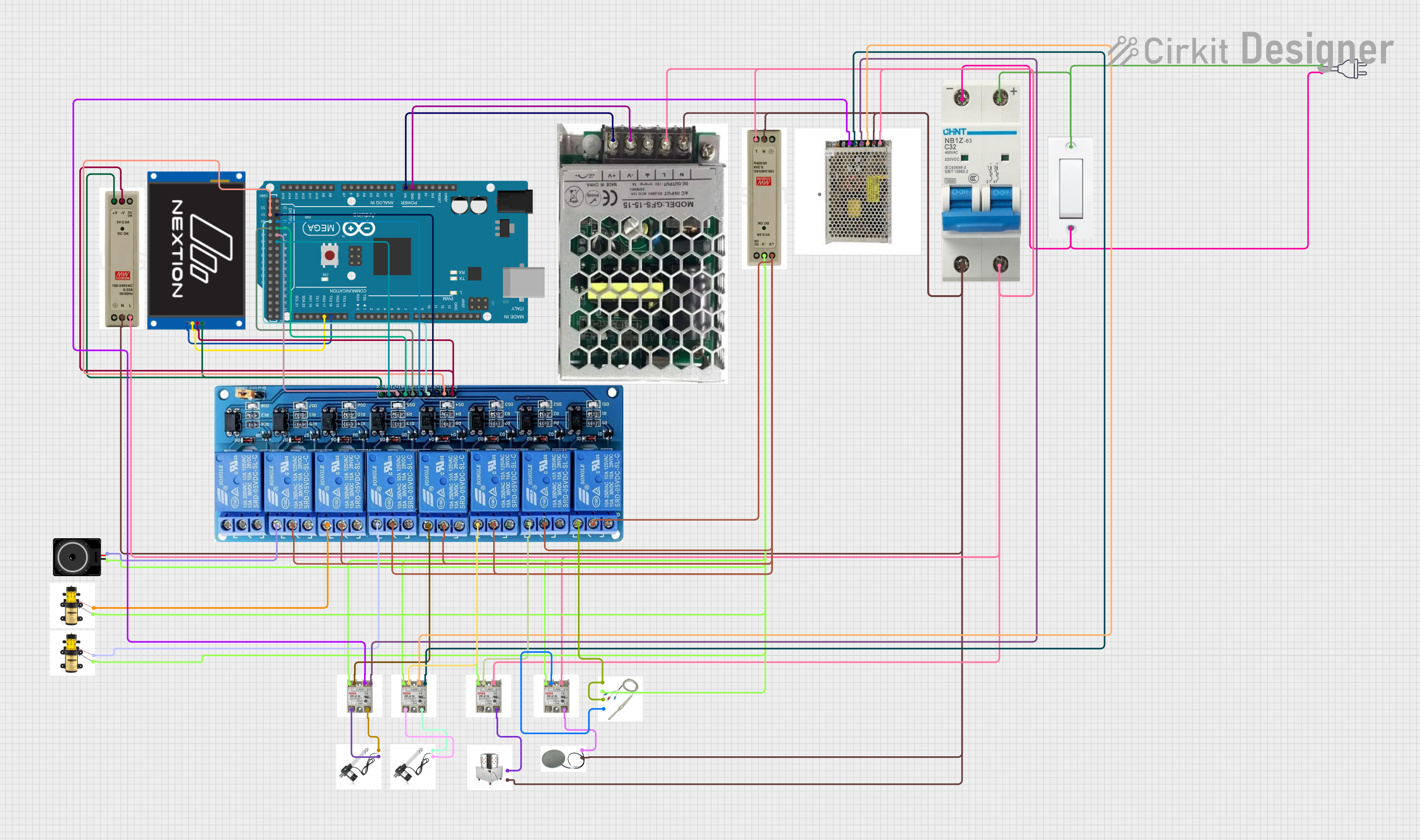
Arduino Mega 2560 Controlled Automation System with 8-Channel Relay and Nextion Touch LCD Interface

This circuit is centered around an Arduino Mega 2560, which controls a Nextion Touch LCD for user interface and a series of relays for switching various loads. The Arduino is powered by a 9V SMPS, and it drives an 8-channel 5V relay module to control devices like pumps, a loudspeaker, actuators, a heating plate, and a plucker. The relays are interfaced with solid-state relays (SSRs) and a thermistor for temperature sensing, enabling controlled power distribution to the connected devices based on programmed logic and user input.
 Open Project in Cirkit Designer
Arduino Nano-Based Environmental Monitoring System with Nextion Touch LCD and CAN BUS Communication

This circuit features an Arduino Nano microcontroller interfaced with a Nextion Touch LCD for user input/output, multiple SSR-10A solid-state relays for controlling high-power devices, and a single-channel relay for additional switching capabilities. It includes an Adafruit MCP9600 for temperature measurements, an MQ-5 gas sensor for detecting gas concentrations, a Hall effect sensor for magnetic field detection, and a CAN BUS module for vehicle communication. The circuit is powered by an LM2596 step-down module and includes various resistors for voltage/current adjustments and protection.
 Open Project in Cirkit Designer
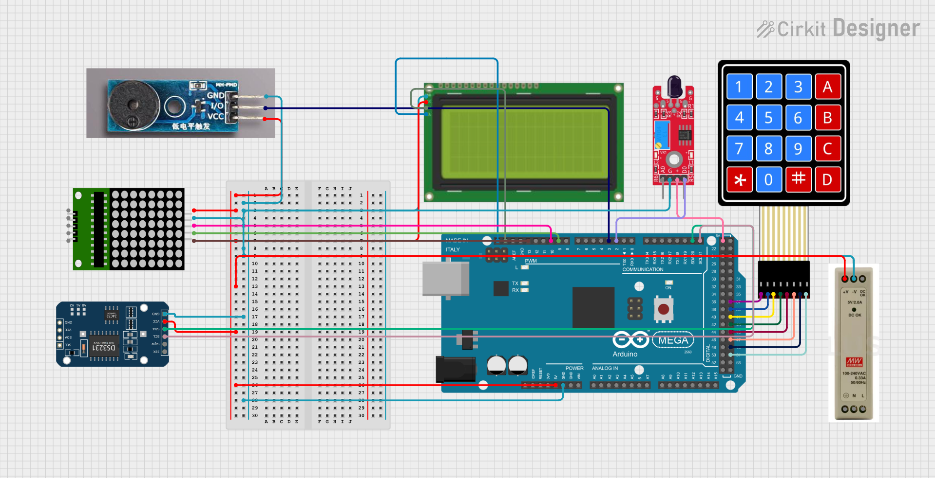
Arduino Mega 2560-Based Smart Home Control System with LCD Display and Flame Sensor

This circuit is a multi-functional embedded system featuring an Arduino Mega 2560 microcontroller that interfaces with a 4x4 membrane keypad, a 20x4 I2C LCD, an 8x8 LED matrix, a DS3231 RTC module, a passive buzzer, and a KY-026 flame sensor. The system is powered by a 5V PSU and is designed to provide real-time clock functionality, user input via the keypad, visual output on the LCD and LED matrix, and flame detection with an audible alert.
 Open Project in Cirkit Designer
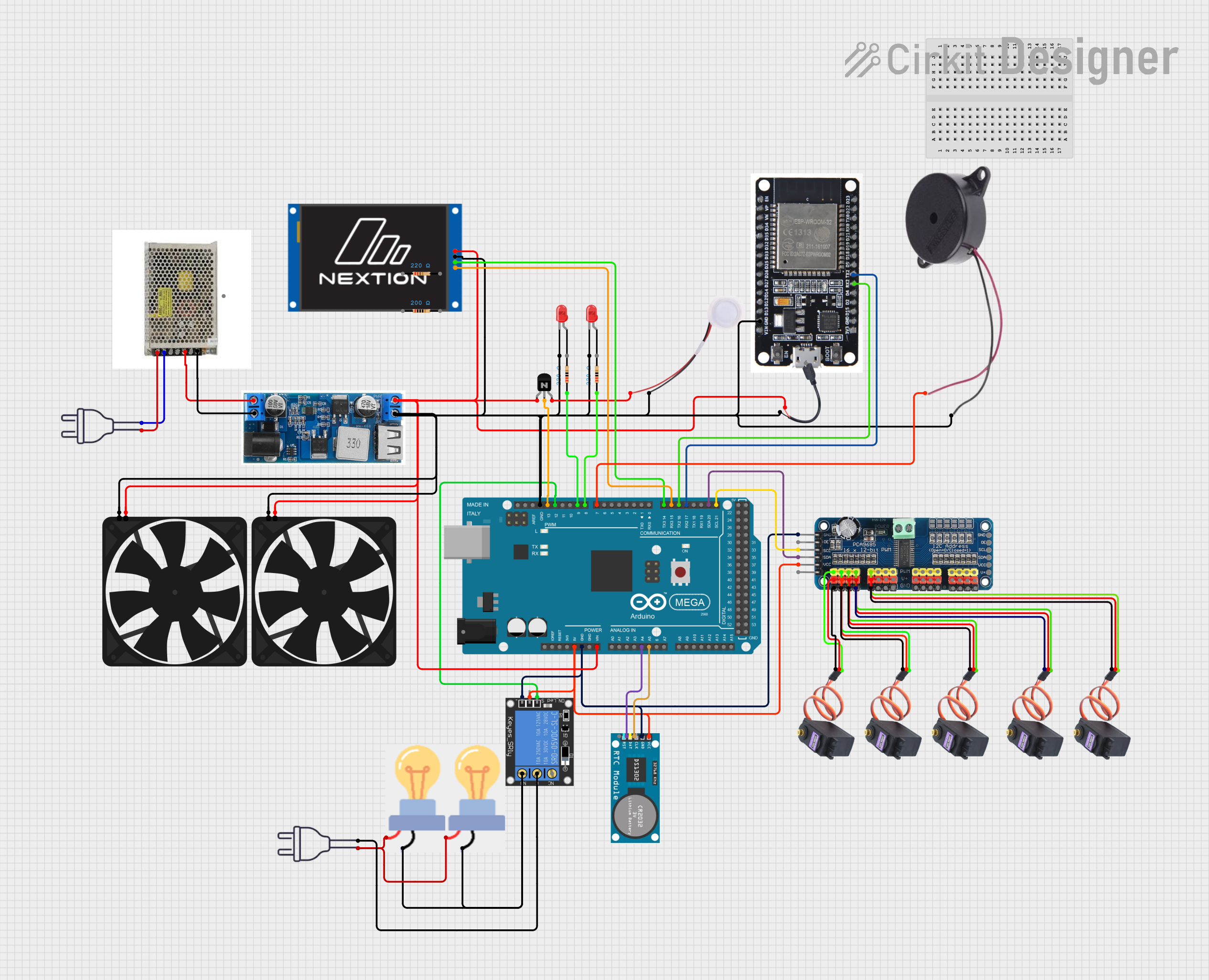
Arduino Mega 2560 and ESP32-Based Smart Home Automation System with Touch LCD and RTC

This circuit is a complex control system utilizing an Arduino Mega 2560 to manage various peripherals including a 16-channel PWM servo driver, an RTC module, a relay, and multiple sensors and actuators such as fans, LEDs, and a humidifier. The system is powered by a 24V DC power supply with a buck converter to step down the voltage, and it includes communication with an ESP32 and a Nextion Touch LCD for user interaction.
 Open Project in Cirkit Designer
Explore Projects Built with Nextion

Arduino Mega 2560 Controlled Automation System with 8-Channel Relay and Nextion Touch LCD Interface
This circuit is centered around an Arduino Mega 2560, which controls a Nextion Touch LCD for user interface and a series of relays for switching various loads. The Arduino is powered by a 9V SMPS, and it drives an 8-channel 5V relay module to control devices like pumps, a loudspeaker, actuators, a heating plate, and a plucker. The relays are interfaced with solid-state relays (SSRs) and a thermistor for temperature sensing, enabling controlled power distribution to the connected devices based on programmed logic and user input.
 Open Project in Cirkit Designer
Arduino Nano-Based Environmental Monitoring System with Nextion Touch LCD and CAN BUS Communication
This circuit features an Arduino Nano microcontroller interfaced with a Nextion Touch LCD for user input/output, multiple SSR-10A solid-state relays for controlling high-power devices, and a single-channel relay for additional switching capabilities. It includes an Adafruit MCP9600 for temperature measurements, an MQ-5 gas sensor for detecting gas concentrations, a Hall effect sensor for magnetic field detection, and a CAN BUS module for vehicle communication. The circuit is powered by an LM2596 step-down module and includes various resistors for voltage/current adjustments and protection.
 Open Project in Cirkit Designer
Arduino Mega 2560-Based Smart Home Control System with LCD Display and Flame Sensor
This circuit is a multi-functional embedded system featuring an Arduino Mega 2560 microcontroller that interfaces with a 4x4 membrane keypad, a 20x4 I2C LCD, an 8x8 LED matrix, a DS3231 RTC module, a passive buzzer, and a KY-026 flame sensor. The system is powered by a 5V PSU and is designed to provide real-time clock functionality, user input via the keypad, visual output on the LCD and LED matrix, and flame detection with an audible alert.
 Open Project in Cirkit Designer
Arduino Mega 2560 and ESP32-Based Smart Home Automation System with Touch LCD and RTC
This circuit is a complex control system utilizing an Arduino Mega 2560 to manage various peripherals including a 16-channel PWM servo driver, an RTC module, a relay, and multiple sensors and actuators such as fans, LEDs, and a humidifier. The system is powered by a 24V DC power supply with a buck converter to step down the voltage, and it includes communication with an ESP32 and a Nextion Touch LCD for user interaction.
 Open Project in Cirkit Designer
Common Applications and Use Cases
- Home Automation: Control and monitor home appliances and systems.
- Industrial Automation: Interface with machinery and industrial processes.
- Medical Devices: Display and control medical equipment parameters.
- Automotive: Infotainment systems and vehicle diagnostics.
- Consumer Electronics: User interfaces for various gadgets and appliances.
Technical Specifications
Key Technical Details
| Specification | Value |
|---|---|
| Display Size | 5 inches |
| Resolution | 800 x 480 pixels |
| Touch Type | Resistive or Capacitive |
| Operating Voltage | 4.75V to 7V |
| Power Consumption | 500mW (typical) |
| Interface | UART (TTL) |
| Flash Memory | 16MB |
| RAM | 3584 bytes |
| Operating Temperature | -20°C to 70°C |
Pin Configuration and Descriptions
| Pin Number | Pin Name | Description |
|---|---|---|
| 1 | VCC | Power supply (4.75V to 7V) |
| 2 | GND | Ground |
| 3 | TX | UART Transmit |
| 4 | RX | UART Receive |
| 5 | NC | Not Connected |
| 6 | NC | Not Connected |
| 7 | NC | Not Connected |
| 8 | NC | Not Connected |
Usage Instructions
How to Use the Component in a Circuit
- Power Supply: Connect the VCC pin to a 5V power supply and the GND pin to the ground.
- UART Communication: Connect the TX pin of the Nextion display to the RX pin of the microcontroller (e.g., Arduino UNO) and the RX pin of the Nextion display to the TX pin of the microcontroller.
- Initialization: Initialize the Nextion display in your microcontroller code to start communication.
Important Considerations and Best Practices
- Power Supply: Ensure a stable power supply to avoid display flickering or malfunction.
- UART Communication: Use appropriate baud rates for reliable communication. The default baud rate is 9600.
- Touch Calibration: Calibrate the touch screen if necessary to ensure accurate touch response.
- Firmware Updates: Keep the display firmware updated for the latest features and bug fixes.
Example Code for Arduino UNO
#include <SoftwareSerial.h>

// Create a software serial port for Nextion communication
SoftwareSerial nextion(2, 3); // RX, TX

void setup() {
  // Start serial communication with Nextion display
  nextion.begin(9600);
  // Start serial communication with the computer
  Serial.begin(9600);
  // Send initialization command to Nextion display
  nextion.print("page 0");
  nextion.write(0xff); // End of command
  nextion.write(0xff); // End of command
  nextion.write(0xff); // End of command
}

void loop() {
  // Check if data is available from Nextion display
  if (nextion.available()) {
    // Read data from Nextion display
    String data = nextion.readString();
    // Print data to the serial monitor
    Serial.println(data);
  }
  // Check if data is available from the computer
  if (Serial.available()) {
    // Read data from the computer
    String data = Serial.readString();
    // Send data to Nextion display
    nextion.print(data);
    nextion.write(0xff); // End of command
    nextion.write(0xff); // End of command
    nextion.write(0xff); // End of command
  }
}
Troubleshooting and FAQs
Common Issues Users Might Face
Display Not Powering On:
- Solution: Check the power connections and ensure a stable 5V supply.
No Communication with Microcontroller:
- Solution: Verify the UART connections and ensure the correct baud rate is set.
Touch Screen Not Responding:
- Solution: Calibrate the touch screen using the Nextion Editor.
Display Flickering:
- Solution: Ensure a stable power supply and check for any loose connections.
Solutions and Tips for Troubleshooting
- Check Connections: Ensure all connections are secure and correctly wired.
- Use Serial Monitor: Use the serial monitor to debug communication issues.
- Update Firmware: Keep the display firmware updated to avoid compatibility issues.
- Consult Documentation: Refer to the Nextion Editor documentation for advanced troubleshooting and configuration options.
By following this documentation, users can effectively integrate and utilize the Nextion 5-Inch HMI Display in their projects, ensuring a smooth and efficient interface design process.