How to Use Exhaust Fan: Examples, Pinouts, and Specs
Introduction
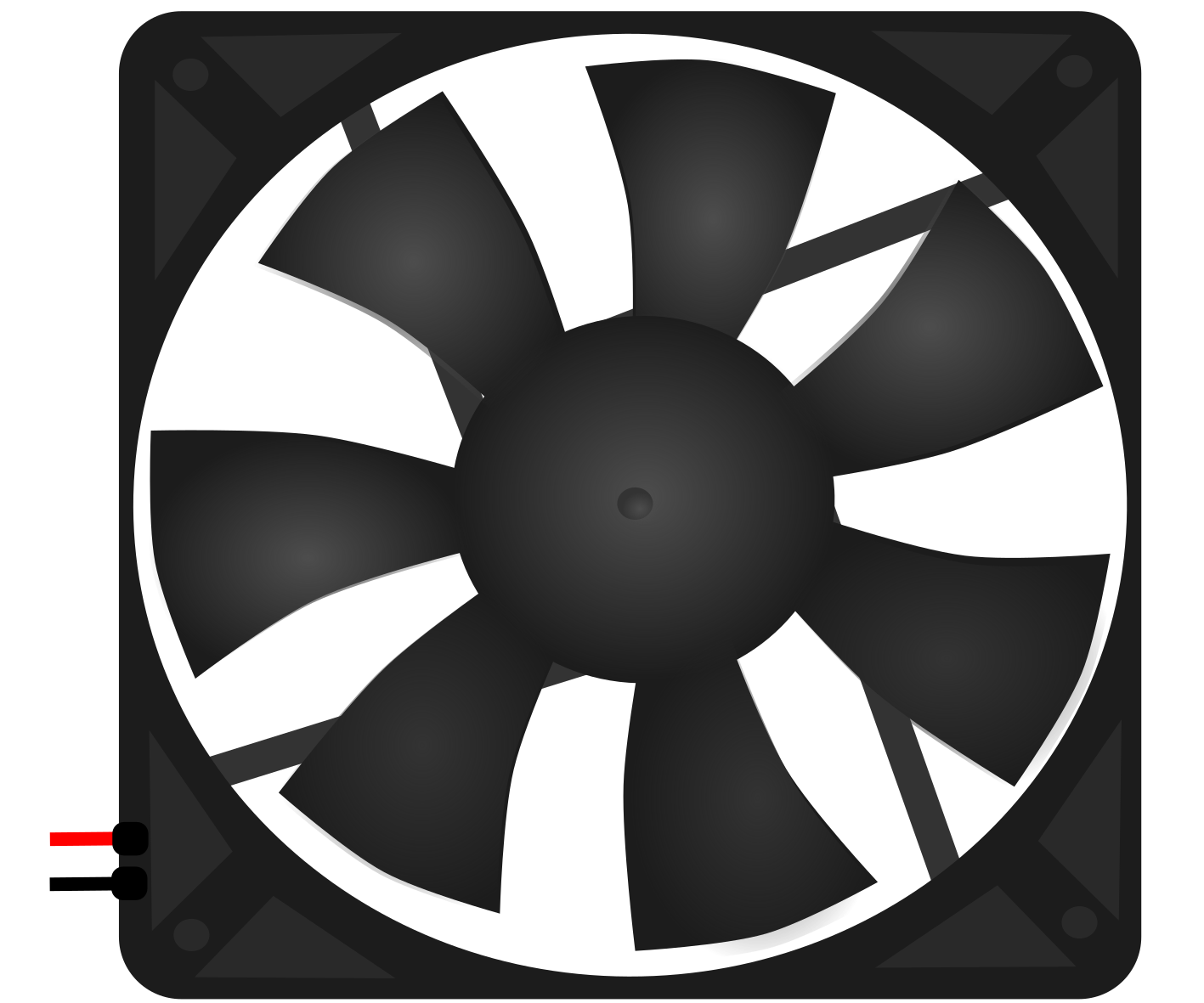
An exhaust fan is a device designed to expel air from an enclosed space, typically to remove heat, moisture, or odors. By improving ventilation and air quality, exhaust fans are essential in various environments, such as kitchens, bathrooms, workshops, and industrial facilities. They help maintain a comfortable and safe atmosphere by preventing the buildup of humidity, smoke, or harmful fumes.
Explore Projects Built with Exhaust Fan
Explore Projects Built with Exhaust Fan
Common Applications and Use Cases
- Residential Use: Ventilation in kitchens, bathrooms, and laundry rooms.
- Industrial Use: Removing fumes, dust, or heat from factories and workshops.
- Commercial Use: Maintaining air quality in restaurants, offices, and retail spaces.
- HVAC Systems: Integrated into heating, ventilation, and air conditioning systems.
Technical Specifications
Below are the general technical specifications for a standard exhaust fan. Specifications may vary depending on the model and manufacturer.
Key Technical Details
- Operating Voltage: 110V AC or 220V AC (varies by region and model)
- Power Consumption: 15W to 100W (depending on size and airflow capacity)
- Airflow Capacity: 50 CFM to 500 CFM (Cubic Feet per Minute)
- Noise Level: 30 dB to 60 dB
- Material: Plastic or metal housing with aluminum or plastic blades
- Mounting Type: Wall-mounted, ceiling-mounted, or window-mounted
- Speed Control: Single-speed or variable-speed options
Pin Configuration and Descriptions
For exhaust fans with an integrated motor and wiring, the following table outlines the typical wire connections:
| Wire Color | Function | Description |
|---|---|---|
| Black | Live (L) | Connects to the live AC power supply. |
| White | Neutral (N) | Connects to the neutral AC power supply. |
| Green/Yellow | Ground (GND) | Provides grounding for safety. |
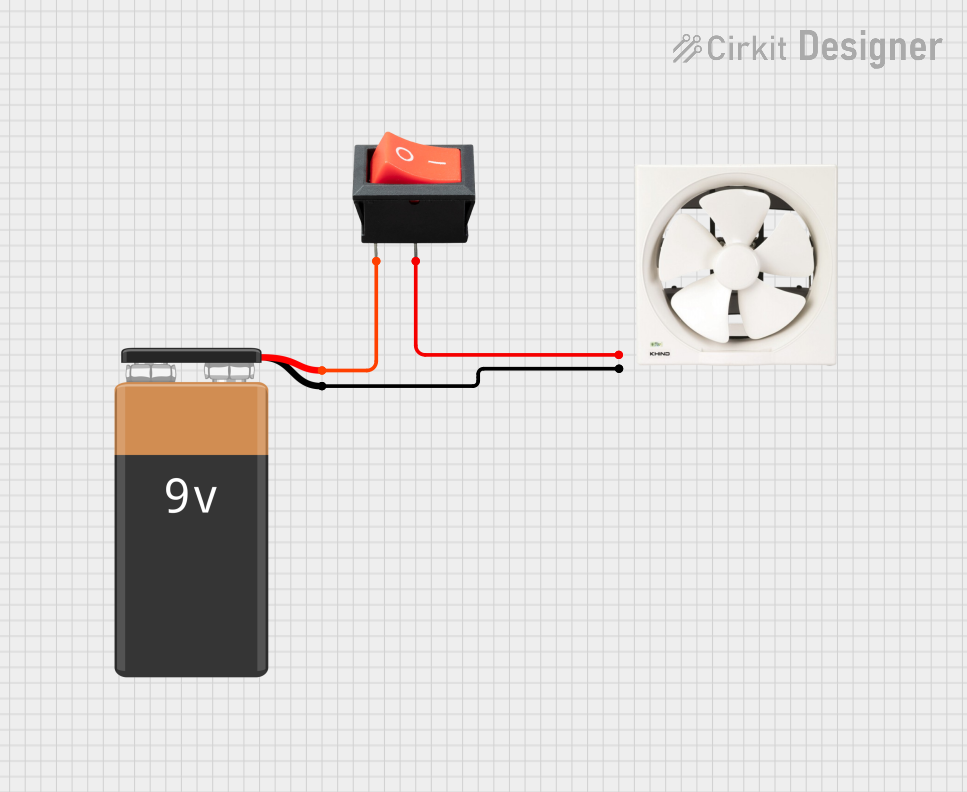
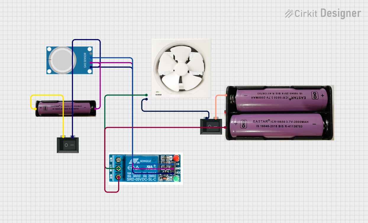
For DC-powered exhaust fans (less common), the pin configuration may look like this:
| Pin | Function | Description |
|---|---|---|
| +V | Positive Voltage Input | Connects to the positive terminal of the power supply. |
| GND | Ground | Connects to the negative terminal of the power supply. |
Usage Instructions
How to Use the Component in a Circuit
- Determine the Power Source: Verify whether the exhaust fan operates on AC or DC power. For AC fans, ensure the voltage matches your region's standard (e.g., 110V or 220V). For DC fans, use an appropriate DC power supply.
- Wiring:
- For AC fans, connect the black wire to the live terminal, the white wire to the neutral terminal, and the green/yellow wire to the ground terminal.
- For DC fans, connect the +V pin to the positive terminal of the power supply and the GND pin to the negative terminal.
- Mounting: Secure the fan in the desired location (e.g., wall, ceiling, or window) using screws or brackets provided by the manufacturer.
- Testing: Turn on the power supply and verify that the fan operates smoothly without unusual noise or vibration.
Important Considerations and Best Practices
- Safety First: Always disconnect the power supply before installing or servicing the fan.
- Proper Ventilation: Ensure the fan is installed in a location where it can effectively expel air to the outside.
- Speed Control: If using a variable-speed fan, ensure the speed controller is compatible with the fan's motor.
- Maintenance: Clean the fan blades and housing periodically to prevent dust buildup, which can reduce efficiency and increase noise.
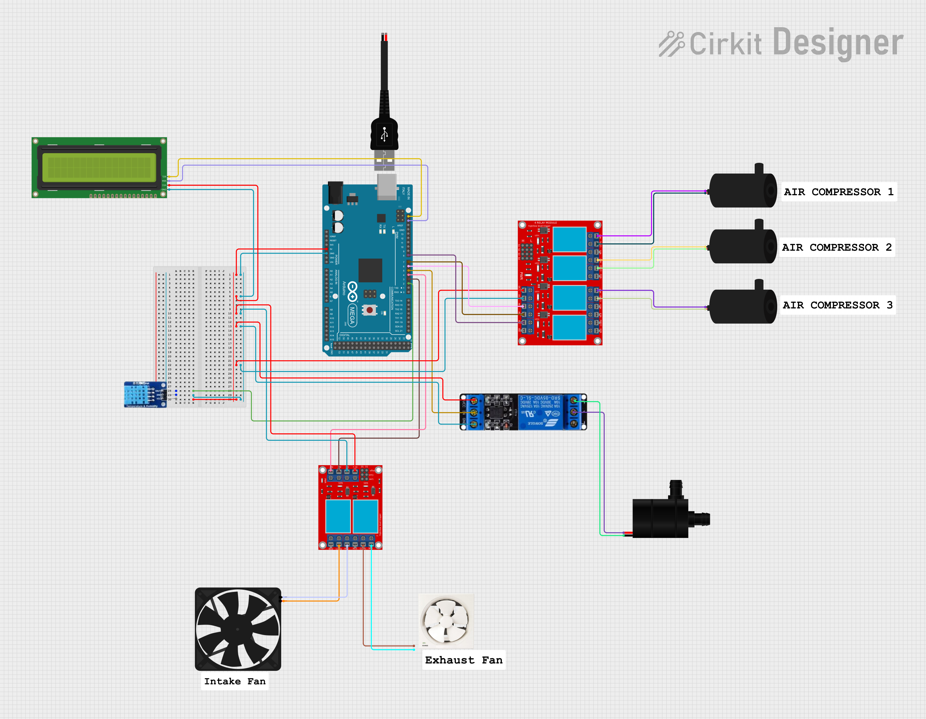
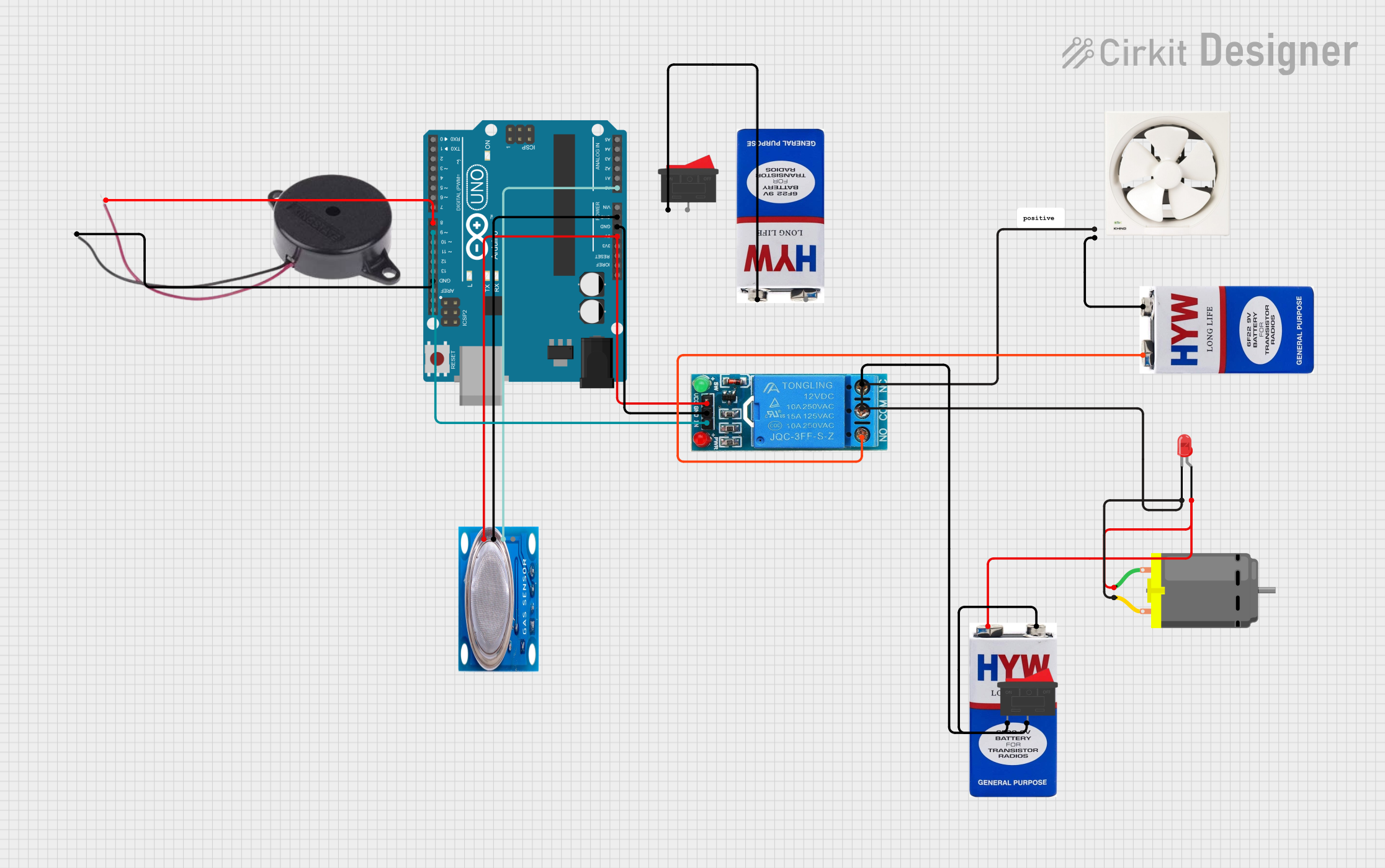
Example: Controlling a DC Exhaust Fan with Arduino UNO
For DC exhaust fans, you can control the fan's speed using an Arduino UNO and a PWM signal. Below is an example code snippet:
// Arduino code to control a DC exhaust fan using PWM
// Connect the fan's +V to a transistor controlled by pin 9
// Connect the fan's GND to the Arduino GND

const int fanPin = 9; // PWM pin connected to the transistor controlling the fan

void setup() {
  pinMode(fanPin, OUTPUT); // Set the fan pin as an output
}

void loop() {
  // Gradually increase fan speed
  for (int speed = 0; speed <= 255; speed += 5) {
    analogWrite(fanPin, speed); // Set fan speed using PWM
    delay(50); // Wait 50ms before increasing speed
  }

  // Gradually decrease fan speed
  for (int speed = 255; speed >= 0; speed -= 5) {
    analogWrite(fanPin, speed); // Set fan speed using PWM
    delay(50); // Wait 50ms before decreasing speed
  }
}
Troubleshooting and FAQs
Common Issues and Solutions
Fan Does Not Turn On:
- Cause: Loose or incorrect wiring.
- Solution: Double-check all connections and ensure the power supply is functioning.
Excessive Noise:
- Cause: Dust buildup or loose mounting.
- Solution: Clean the fan blades and housing. Tighten all mounting screws.
Fan Vibrates Excessively:
- Cause: Imbalanced blades or improper installation.
- Solution: Inspect the blades for damage and ensure the fan is securely mounted.
Fan Runs at Low Speed:
- Cause: Insufficient power supply or faulty motor.
- Solution: Verify the power supply voltage and inspect the motor for defects.
FAQs
Can I use an exhaust fan with a dimmer switch?
- Only if the fan is compatible with dimmer switches. Check the manufacturer's specifications.
How do I calculate the required CFM for my space?
- Multiply the room's volume (length × width × height) by the desired air changes per hour (ACH), then divide by 60.
Can I use an exhaust fan outdoors?
- Only if the fan is rated for outdoor use. Look for weatherproof or IP-rated models.
By following this documentation, you can effectively install, use, and maintain an exhaust fan for optimal performance and longevity.