How to Use Arduino Mega 2560: Examples, Pinouts, and Specs
Introduction
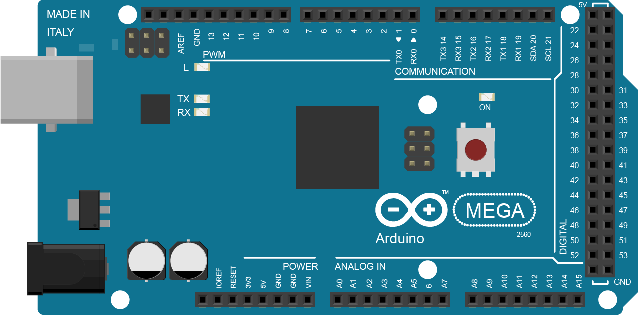
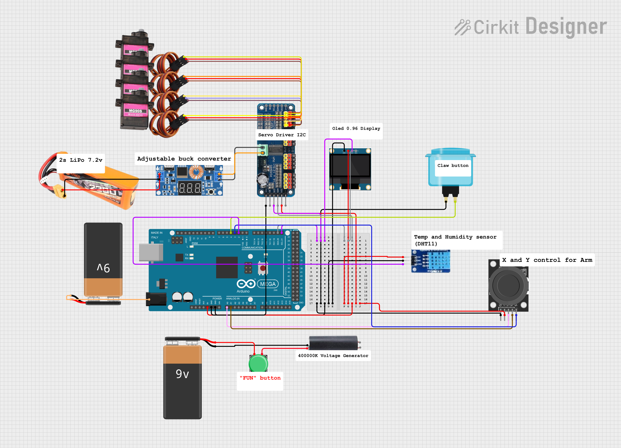
The Arduino Mega 2560 is a powerful microcontroller board based on the ATmega2560. It features 54 digital input/output pins (15 of which can be used as PWM outputs), 16 analog inputs, 4 UARTs (hardware serial ports), a 16 MHz crystal oscillator, a USB connection, a power jack, an ICSP header, and a reset button. This board is ideal for projects requiring a large number of I/O pins or complex functionality, such as robotics, IoT systems, and advanced prototyping.
Explore Projects Built with Arduino Mega 2560
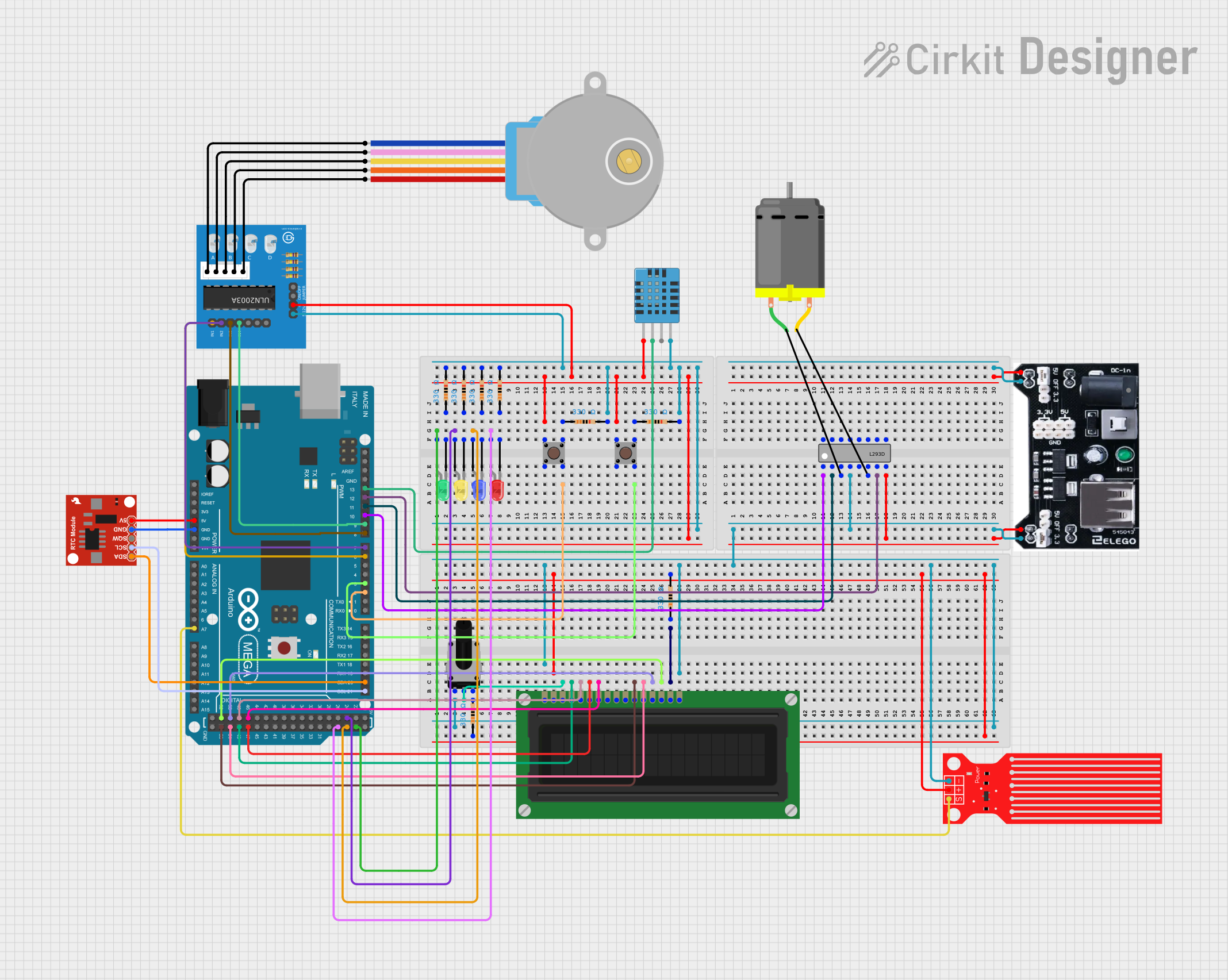
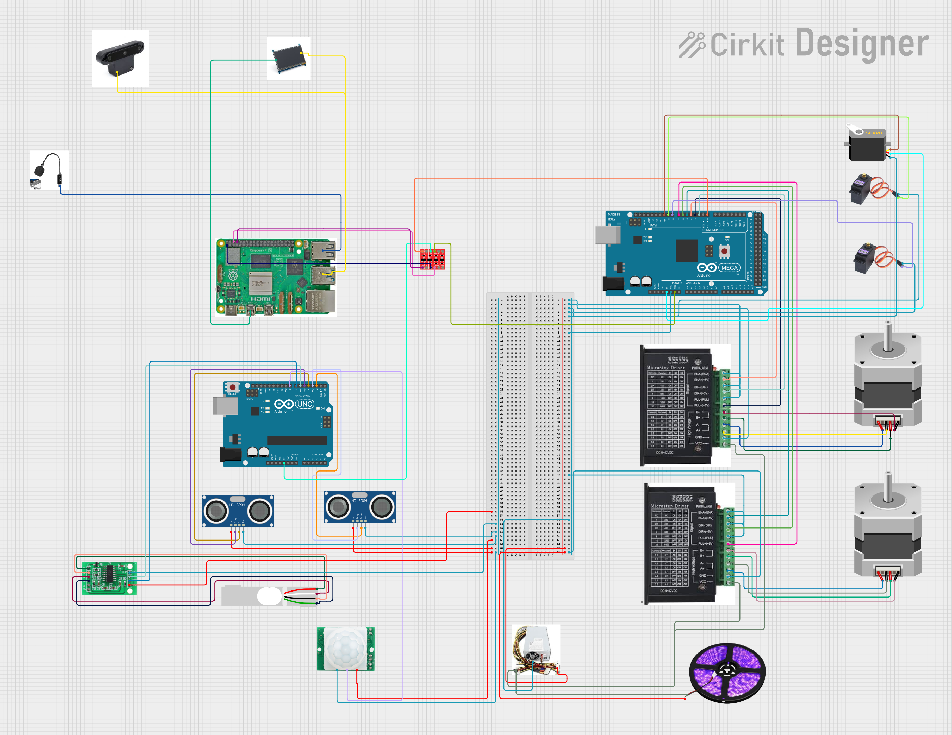
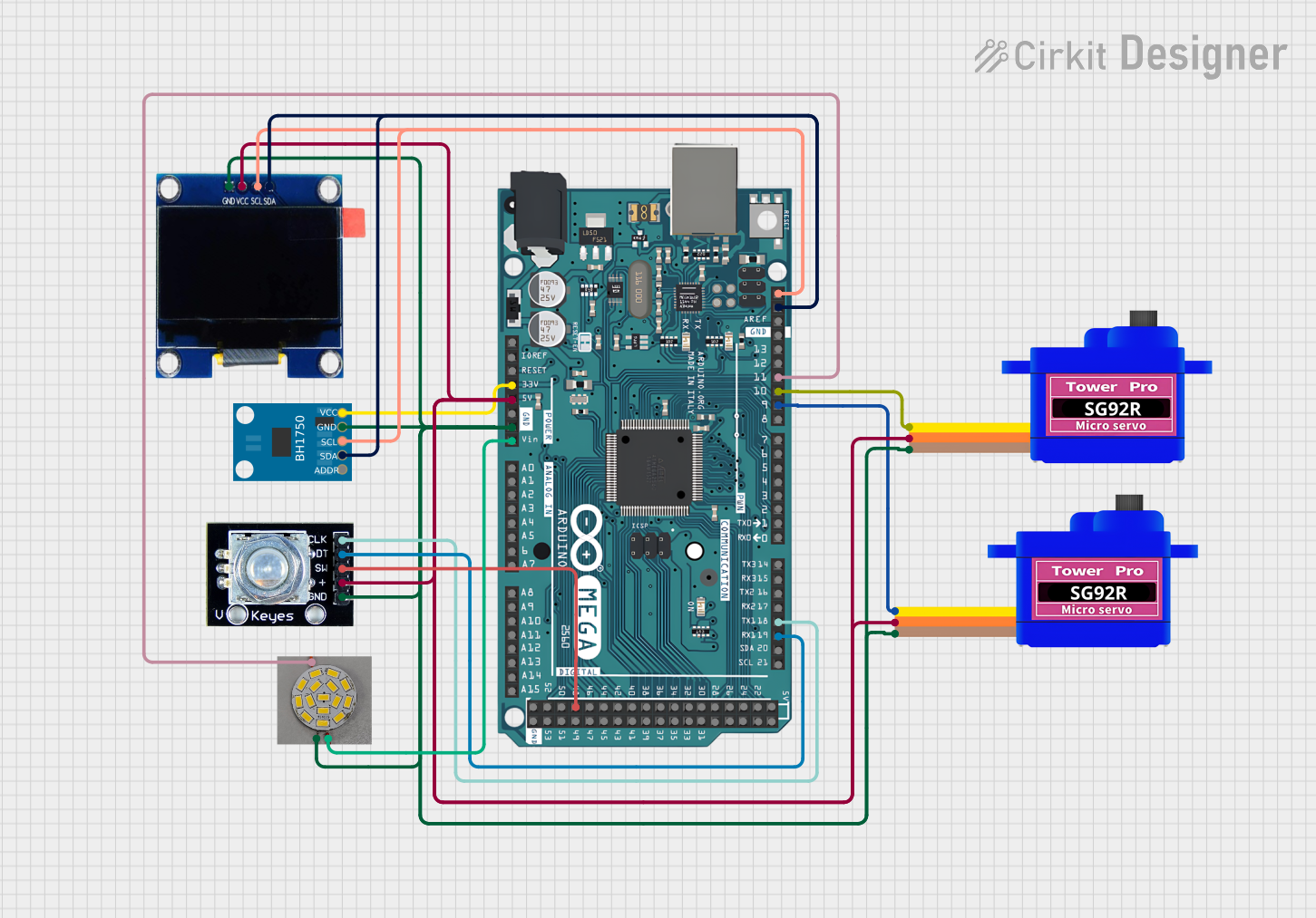
Explore Projects Built with Arduino Mega 2560
Common Applications and Use Cases
- Robotics and automation systems
- IoT (Internet of Things) devices
- Data acquisition and logging
- Complex sensor networks
- Prototyping for large-scale embedded systems
- Educational projects requiring multiple peripherals
Technical Specifications
Key Technical Details
| Specification | Value |
|---|---|
| Microcontroller | ATmega2560 |
| Operating Voltage | 5V |
| Input Voltage (recommended) | 7-12V |
| Input Voltage (limit) | 6-20V |
| Digital I/O Pins | 54 (15 PWM outputs) |
| Analog Input Pins | 16 |
| DC Current per I/O Pin | 20 mA |
| Flash Memory | 256 KB (8 KB used by bootloader) |
| SRAM | 8 KB |
| EEPROM | 4 KB |
| Clock Speed | 16 MHz |
| USB Connector | Type-B |
| Dimensions | 101.52 mm x 53.3 mm |
| Weight | 37 g |
Pin Configuration and Descriptions
Digital Pins
| Pin Number | Functionality |
|---|---|
| 0-1 | UART0 (Serial communication) |
| 2-13 | General-purpose digital I/O |
| 3, 5, 6, 9, 10, 11 | PWM outputs |
| 20-21 | I2C (SDA, SCL) |
| 22-53 | General-purpose digital I/O |
Analog Pins
| Pin Number | Functionality |
|---|---|
| A0-A15 | Analog inputs (10-bit resolution) |
Power Pins
| Pin Name | Description |
|---|---|
| VIN | Input voltage to the board |
| 5V | Regulated 5V output |
| 3.3V | Regulated 3.3V output |
| GND | Ground |
| IOREF | Voltage reference for I/O pins |
| RESET | Reset the microcontroller |
Usage Instructions
How to Use the Arduino Mega 2560 in a Circuit
Powering the Board:
- Connect the board to your computer via the USB Type-B cable for programming and power.
- Alternatively, use an external power supply (7-12V) via the DC power jack or VIN pin.
Programming:
- Install the Arduino IDE from the official Arduino website.
- Select "Arduino Mega 2560" as the board type in the Tools menu.
- Choose the correct COM port for the board.
- Write or load your sketch and click the upload button.
Connecting Components:
- Use the digital pins for digital sensors, actuators, or communication modules.
- Use the analog pins for sensors that output analog signals.
- Connect external modules (e.g., LCDs, motors, or shields) to the appropriate pins.
Important Considerations and Best Practices
- Avoid exceeding the maximum current rating (20 mA per I/O pin).
- Use external power when driving high-current devices like motors or LEDs.
- Use pull-up or pull-down resistors for stable digital input signals.
- Ensure proper grounding between the Arduino and external components.
- Use decoupling capacitors for noise-sensitive circuits.
Example Code for Arduino Mega 2560
The following example demonstrates how to blink an LED connected to pin 13:
// Blink an LED connected to pin 13
// This example toggles the LED on and off every second.

void setup() {
  pinMode(13, OUTPUT); // Set pin 13 as an output
}

void loop() {
  digitalWrite(13, HIGH); // Turn the LED on
  delay(1000);            // Wait for 1 second
  digitalWrite(13, LOW);  // Turn the LED off
  delay(1000);            // Wait for 1 second
}
Troubleshooting and FAQs
Common Issues and Solutions
The board is not recognized by the computer:
- Ensure the USB cable is functional and properly connected.
- Install the necessary drivers for the Arduino Mega 2560.
- Check if the correct COM port is selected in the Arduino IDE.
Sketch upload fails:
- Verify that "Arduino Mega 2560" is selected as the board type.
- Ensure no other program is using the COM port.
- Press the reset button on the board before uploading.
Components connected to the board are not working:
- Double-check the wiring and connections.
- Ensure the components are compatible with the Arduino Mega 2560.
- Verify that the correct pins are defined in the code.
The board overheats:
- Check for short circuits in the wiring.
- Avoid drawing excessive current from the I/O pins.
FAQs
Q: Can I use the Arduino Mega 2560 with shields designed for the Arduino Uno?
A: Yes, most shields are compatible with the Mega 2560, but ensure the shield does not rely on pins that differ between the two boards.
Q: How do I reset the board?
A: Press the reset button on the board or connect the RESET pin to GND momentarily.
Q: Can I power the board with a battery?
A: Yes, you can use a 9V battery connected to the DC power jack or VIN pin.
Q: What is the maximum current the board can supply?
A: The 5V pin can supply up to 500 mA when powered via USB or up to 1A when using an external power supply.