How to Use DDCS V3.1 CNC Controller: Examples, Pinouts, and Specs
Introduction
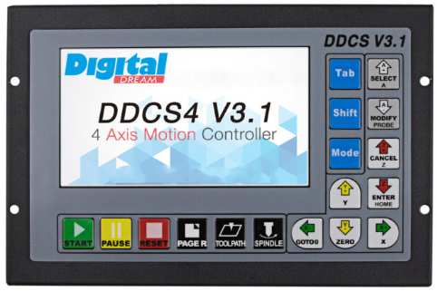
The DDCS V3.1 CNC Controller, manufactured by DDCS, is a digital controller designed for managing CNC (Computer Numerical Control) machines. It provides precise control over stepper or servo motors, enabling automated machining processes with high accuracy and efficiency. This standalone controller is equipped with a user-friendly interface, eliminating the need for a PC during operation. It is widely used in CNC milling, engraving, plasma cutting, and other automated machining applications.
Explore Projects Built with DDCS V3.1 CNC Controller
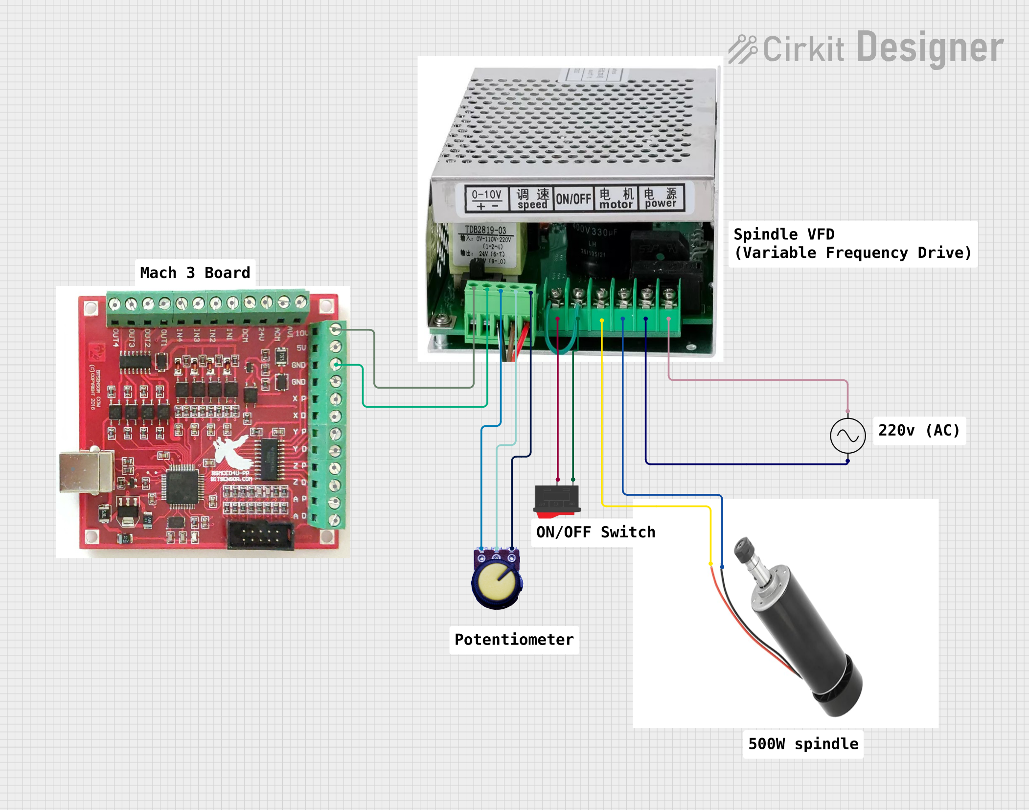
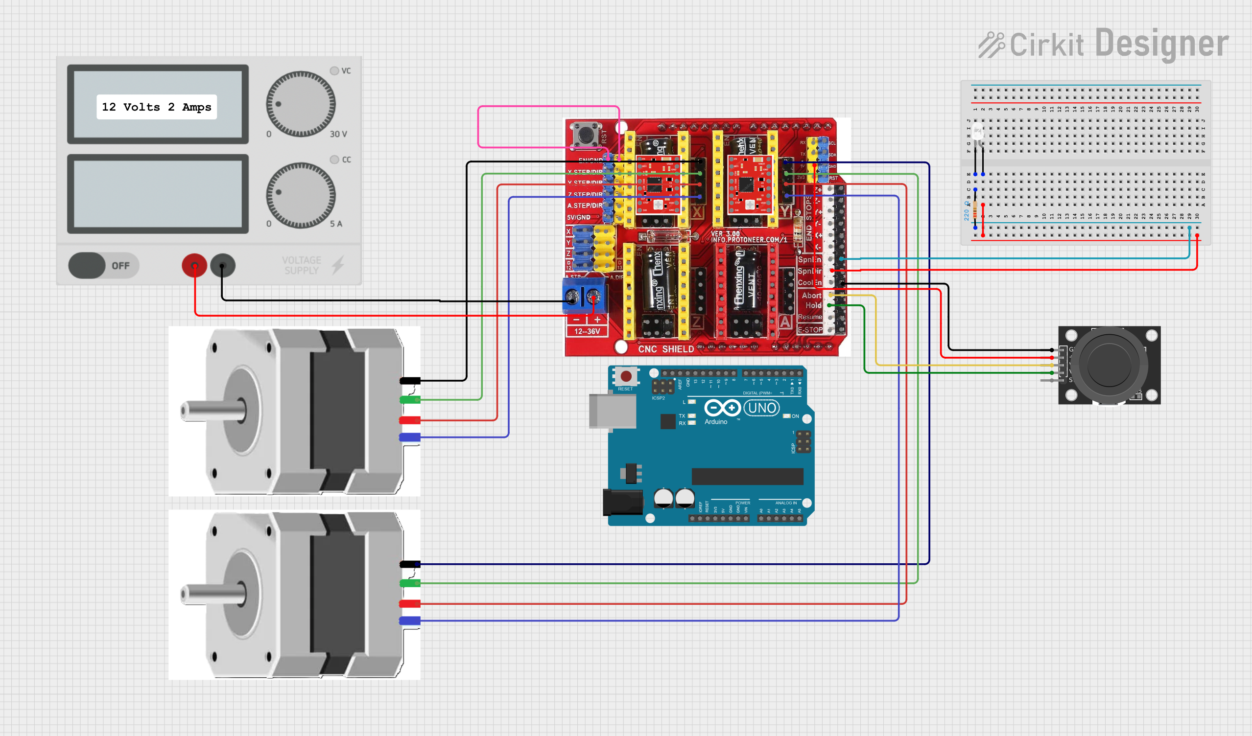
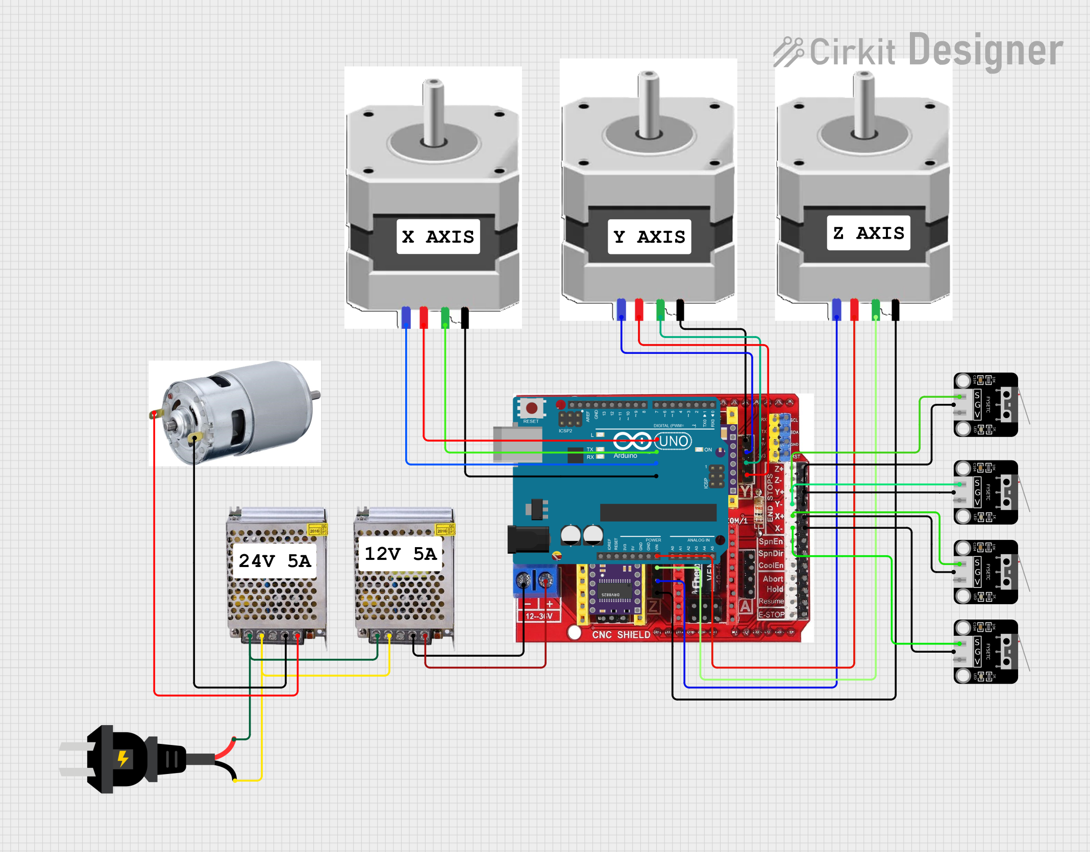

Explore Projects Built with DDCS V3.1 CNC Controller
Common Applications and Use Cases
- CNC milling machines for precision machining
- CNC engraving machines for intricate designs
- Plasma cutting systems for metal fabrication
- Woodworking CNC routers
- Industrial automation requiring precise motor control
Technical Specifications
The DDCS V3.1 CNC Controller is a robust and versatile device with the following key specifications:
| Parameter | Specification |
|---|---|
| Manufacturer | DDCS |
| Model | DDCS V3.1 |
| Input Voltage | 24V DC |
| Maximum Current | 0.5A |
| Axis Control | 4-axis simultaneous control (X, Y, Z, A) |
| Display | 7-inch TFT LCD touchscreen |
| Supported Motors | Stepper motors and servo motors |
| Pulse Frequency | Up to 500 kHz |
| Communication Interface | USB (for G-code file transfer) |
| Storage | Supports USB flash drives for program storage |
| Supported File Formats | G-code (standard CNC programming language) |
| Operating Temperature | 0°C to 50°C |
| Dimensions | 200mm x 130mm x 50mm |
| Weight | Approximately 1.2 kg |
Pin Configuration and Descriptions
The DDCS V3.1 CNC Controller features multiple input and output terminals for connecting motors, sensors, and other peripherals. Below is the pin configuration:
Motor Control Pins
| Pin Name | Description |
|---|---|
| X+, X- | Step and direction signals for X-axis motor |
| Y+, Y- | Step and direction signals for Y-axis motor |
| Z+, Z- | Step and direction signals for Z-axis motor |
| A+, A- | Step and direction signals for A-axis motor |
Input/Output Pins
| Pin Name | Description |
|---|---|
| IN1 - IN8 | Configurable input pins for limit switches, probes, etc. |
| OUT1 - OUT4 | Configurable output pins for controlling relays, spindles, etc. |
Power and Communication Pins
| Pin Name | Description |
|---|---|
| 24V, GND | Power supply input (24V DC) |
| USB | USB port for G-code file transfer |
Usage Instructions
How to Use the DDCS V3.1 in a Circuit
- Power Connection: Connect a 24V DC power supply to the 24V and GND terminals.
- Motor Connection: Connect the stepper or servo motors to the respective axis terminals (X+, X-, Y+, Y-, etc.).
- Input Devices: Attach limit switches, probes, or other input devices to the IN1-IN8 terminals.
- Output Devices: Connect relays, spindles, or other output devices to the OUT1-OUT4 terminals.
- G-code Transfer: Use a USB flash drive to load G-code files into the controller.
- Operation: Use the 7-inch touchscreen to configure settings, load programs, and control the CNC machine.
Important Considerations and Best Practices
- Ensure the power supply voltage is stable and within the specified range (24V DC).
- Use shielded cables for motor connections to minimize electromagnetic interference.
- Properly configure limit switches to prevent over-travel and damage to the machine.
- Regularly update the firmware (if applicable) to ensure optimal performance.
- Always verify G-code files for errors before running them on the machine.
Example: Connecting to an Arduino UNO
While the DDCS V3.1 is a standalone controller, it can be interfaced with an Arduino UNO for additional functionality, such as custom sensor integration. Below is an example Arduino sketch for sending a signal to the DDCS controller:
// Example Arduino code to send a signal to the DDCS V3.1 CNC Controller
// This code toggles an output pin to simulate a signal (e.g., spindle control).

const int outputPin = 7; // Pin connected to DDCS input (e.g., IN1)

void setup() {
  pinMode(outputPin, OUTPUT); // Set the pin as an output
}

void loop() {
  digitalWrite(outputPin, HIGH); // Send a HIGH signal
  delay(1000); // Wait for 1 second
  digitalWrite(outputPin, LOW);  // Send a LOW signal
  delay(1000); // Wait for 1 second
}
Troubleshooting and FAQs
Common Issues and Solutions
Controller Does Not Power On
- Cause: Insufficient or incorrect power supply.
- Solution: Verify that the power supply provides 24V DC and is properly connected.
Motors Not Moving
- Cause: Incorrect wiring or configuration.
- Solution: Check motor connections and ensure the correct step and direction signals are assigned in the controller settings.
Limit Switches Not Responding
- Cause: Faulty wiring or incorrect input configuration.
- Solution: Verify the wiring of the limit switches and ensure they are assigned to the correct input pins.
G-code File Not Loading
- Cause: Unsupported file format or corrupted USB drive.
- Solution: Ensure the G-code file is in the correct format and the USB drive is functioning properly.
Touchscreen Not Responding
- Cause: Calibration issue or hardware fault.
- Solution: Recalibrate the touchscreen or contact the manufacturer for support.
FAQs
Q: Can the DDCS V3.1 control more than 4 axes?
A: No, the DDCS V3.1 is designed for 4-axis control only (X, Y, Z, A).
Q: Does the controller support Ethernet or Wi-Fi?
A: No, the DDCS V3.1 only supports USB for file transfer.
Q: What is the maximum file size for G-code programs?
A: The maximum file size depends on the capacity of the USB flash drive used.
Q: Can I use the DDCS V3.1 with servo motors?
A: Yes, the controller supports both stepper and servo motors.
Q: Is the firmware upgradable?
A: Yes, firmware updates can be applied via USB if provided by the manufacturer.