How to Use hdmi 3row: Examples, Pinouts, and Specs
Introduction
The HDMI 3-Row Connector (Manufacturer: AKB, Part ID: 1234) is a high-performance interface designed for transmitting high-definition video and audio signals between devices. This connector features a 3-row pin configuration, ensuring reliable and efficient data transfer. It is widely used in consumer electronics, including televisions, monitors, gaming consoles, and home theater systems.
Explore Projects Built with hdmi 3row


Explore Projects Built with hdmi 3row
Common Applications and Use Cases
- Connecting high-definition displays to source devices (e.g., Blu-ray players, gaming consoles, PCs)
- Audio-visual setups in home theaters
- Professional video production equipment
- Digital signage and multimedia systems
Technical Specifications
The HDMI 3-Row Connector is designed to meet the requirements of modern high-definition multimedia systems. Below are its key technical details:
Key Technical Details
| Parameter | Specification |
|---|---|
| Manufacturer | AKB |
| Part ID | 1234 |
| Connector Type | HDMI (High-Definition Multimedia Interface) |
| Pin Configuration | 3-row, 19 pins |
| Supported Resolutions | Up to 4K UHD (3840x2160) at 60Hz |
| Audio Support | Multi-channel digital audio |
| Voltage Rating | 5V DC |
| Current Rating | 0.5A per pin |
| Operating Temperature | -20°C to 85°C |
| Durability | 10,000 mating cycles |
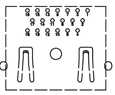
Pin Configuration and Descriptions
The HDMI 3-Row Connector features 19 pins arranged in three rows. Below is the pinout and description:
| Pin Number | Signal Name | Description |
|---|---|---|
| 1 | TMDS Data2+ | Positive differential signal for TMDS channel 2 |
| 2 | TMDS Data2 Shield | Shield for TMDS channel 2 |
| 3 | TMDS Data2- | Negative differential signal for TMDS channel 2 |
| 4 | TMDS Data1+ | Positive differential signal for TMDS channel 1 |
| 5 | TMDS Data1 Shield | Shield for TMDS channel 1 |
| 6 | TMDS Data1- | Negative differential signal for TMDS channel 1 |
| 7 | TMDS Data0+ | Positive differential signal for TMDS channel 0 |
| 8 | TMDS Data0 Shield | Shield for TMDS channel 0 |
| 9 | TMDS Data0- | Negative differential signal for TMDS channel 0 |
| 10 | TMDS Clock+ | Positive differential signal for TMDS clock |
| 11 | TMDS Clock Shield | Shield for TMDS clock |
| 12 | TMDS Clock- | Negative differential signal for TMDS clock |
| 13 | CEC | Consumer Electronics Control |
| 14 | Reserved (N.C.) | Reserved, no connection |
| 15 | SCL | I2C Serial Clock for DDC |
| 16 | SDA | I2C Serial Data for DDC |
| 17 | DDC/CEC Ground | Ground for DDC and CEC |
| 18 | +5V Power | +5V DC power supply |
| 19 | Hot Plug Detect | Signal to detect connected devices |
Usage Instructions
How to Use the HDMI 3-Row Connector in a Circuit
- Mounting the Connector: Secure the HDMI 3-Row Connector to the PCB using the appropriate soldering technique. Ensure all pins are properly aligned and soldered to avoid connectivity issues.
- Connecting Devices: Use a standard HDMI cable to connect the source device (e.g., Blu-ray player, PC) to the display or receiver.
- Power Supply: Ensure the +5V power pin (Pin 18) is supplied with a stable 5V DC source. This is necessary for proper operation of the HDMI interface.
- Signal Integrity: Use high-quality HDMI cables to minimize signal degradation, especially for high-resolution video (e.g., 4K UHD).
Important Considerations and Best Practices
- Cable Length: For resolutions up to 4K UHD, use HDMI cables shorter than 15 meters to maintain signal integrity.
- Shielding: Ensure proper grounding and shielding to reduce electromagnetic interference (EMI).
- Hot Plugging: Avoid frequent hot plugging (connecting/disconnecting while powered) to prevent wear and tear on the connector.
- Compatibility: Verify that the connected devices support the same HDMI version and features (e.g., 4K, HDR).
Example: Using with an Arduino UNO
The HDMI 3-Row Connector can be used with an Arduino UNO for basic CEC (Consumer Electronics Control) communication. Below is an example code snippet:
#include <Wire.h> // Include the I2C library for DDC communication

#define CEC_PIN 13 // Define the pin connected to the CEC line

void setup() {
  pinMode(CEC_PIN, OUTPUT); // Set the CEC pin as an output
  digitalWrite(CEC_PIN, LOW); // Initialize the CEC line to LOW
  Serial.begin(9600); // Start serial communication for debugging
  Serial.println("HDMI CEC Communication Initialized");
}

void loop() {
  // Example: Send a simple CEC signal
  digitalWrite(CEC_PIN, HIGH); // Set the CEC line HIGH
  delay(1); // Hold for 1ms
  digitalWrite(CEC_PIN, LOW); // Set the CEC line LOW
  delay(1000); // Wait for 1 second before repeating

  // Debugging output
  Serial.println("CEC signal sent");
}
Note: This example demonstrates basic control of the CEC line. For full HDMI CEC functionality, additional libraries and protocols are required.
Troubleshooting and FAQs
Common Issues and Solutions
No Signal Detected on Display
- Cause: Loose or improperly connected HDMI cable.
- Solution: Ensure the HDMI cable is securely connected to both the source and display devices.
Intermittent Signal Loss
- Cause: Poor-quality HDMI cable or excessive cable length.
- Solution: Use a high-quality HDMI cable and keep the cable length within recommended limits.
Audio Not Transmitted
- Cause: Incorrect audio settings on the source device.
- Solution: Check the audio output settings on the source device and ensure HDMI audio is enabled.
Connector Pins Damaged
- Cause: Frequent hot plugging or improper handling.
- Solution: Replace the damaged connector and avoid excessive hot plugging.
FAQs
Q: Can this connector support 8K resolution?
A: No, the HDMI 3-Row Connector (AKB 1234) supports resolutions up to 4K UHD at 60Hz. For 8K support, a newer HDMI version is required.
Q: Is this connector backward compatible with older HDMI devices?
A: Yes, HDMI is designed to be backward compatible. However, features like 4K or HDR may not be available on older devices.
Q: Can I use this connector for power delivery?
A: The HDMI 3-Row Connector provides a +5V power pin (Pin 18) for low-power applications, but it is not designed for high-power delivery.
Q: How do I clean the connector?
A: Use a soft, dry cloth or compressed air to remove dust and debris. Avoid using liquids or abrasive materials.