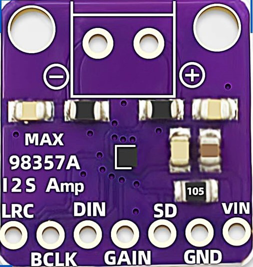
How to Use AMP: Examples, Pinouts, and Specs
Introduction
An amplifier (AMP) is an electronic device designed to increase the power, voltage, or current of an input signal. Amplifiers are essential components in a wide range of electronic systems, as they enhance signal strength to drive other devices or systems effectively. They are commonly used in audio equipment (e.g., speakers, microphones), radio transmission, instrumentation, and communication systems.
Explore Projects Built with AMP
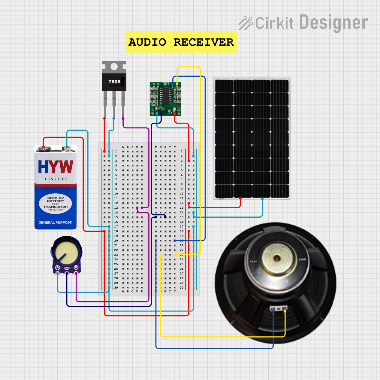

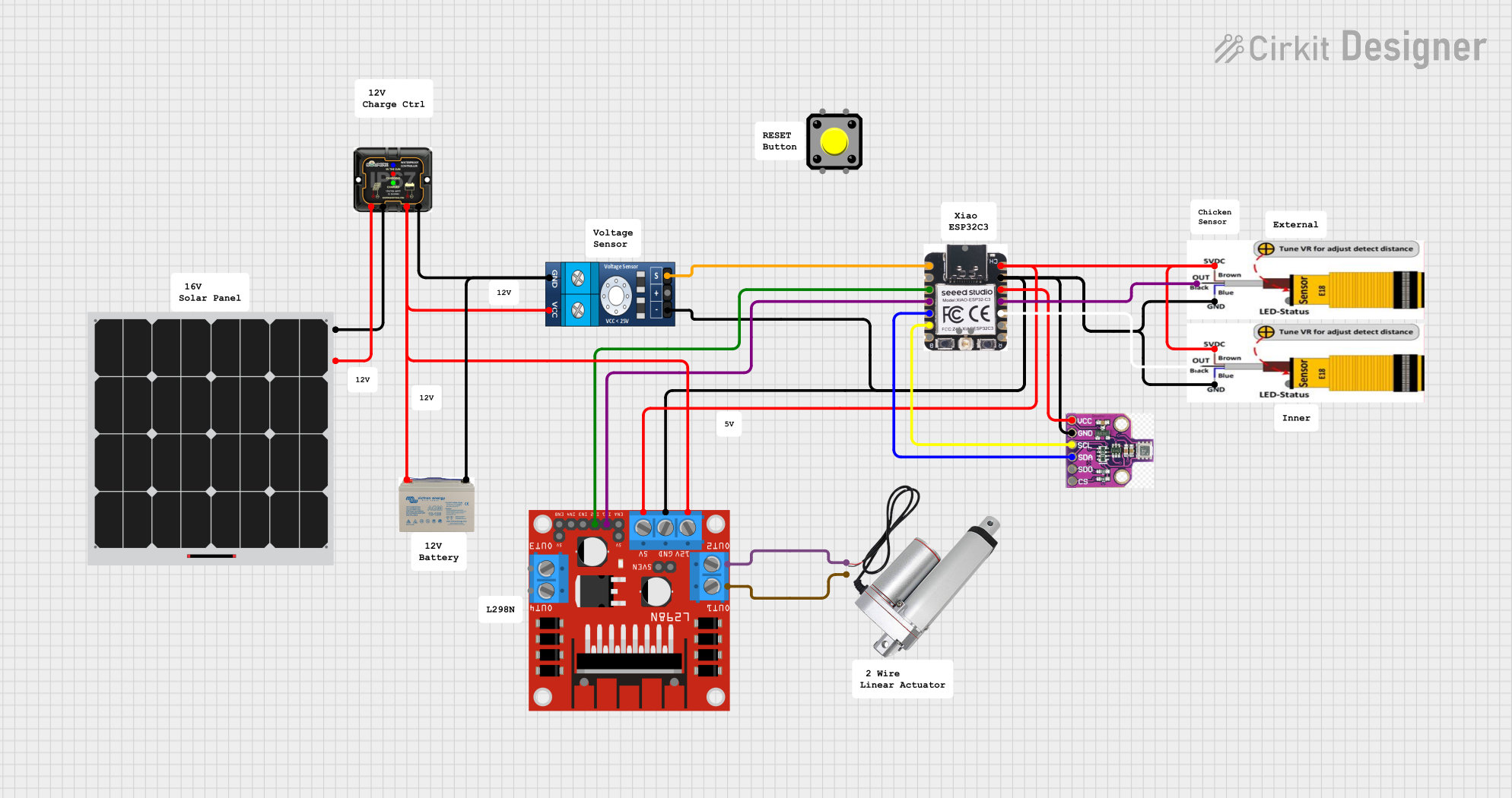
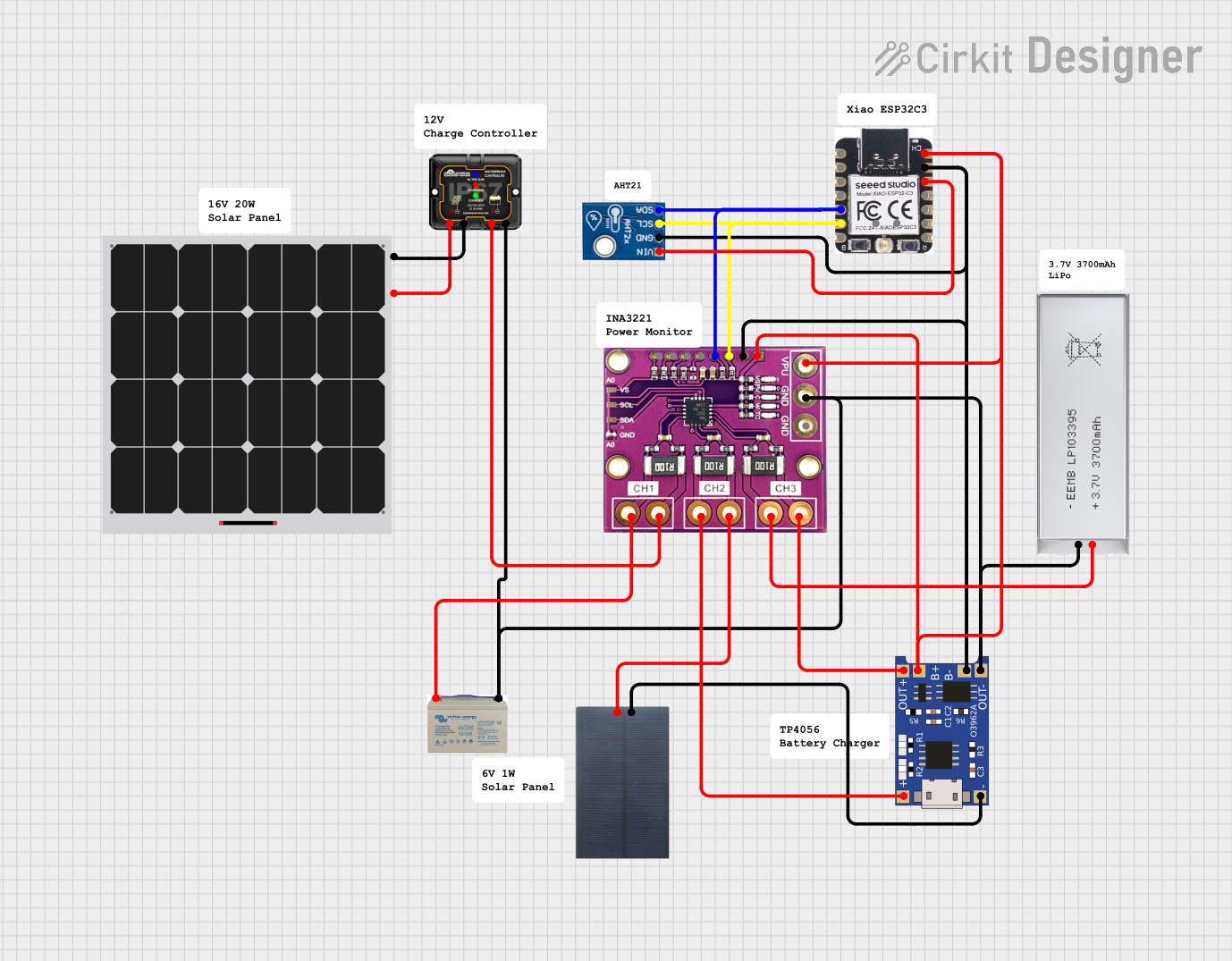
Explore Projects Built with AMP
Common Applications and Use Cases
- Audio Systems: Amplifying sound signals for speakers and headphones.
- Radio Frequency (RF) Systems: Boosting weak RF signals for transmission or reception.
- Instrumentation: Enhancing sensor signals for accurate measurement and processing.
- Communication Systems: Strengthening signals in telecommunication networks.
- Power Electronics: Driving motors or actuators in industrial applications.
Technical Specifications
The technical specifications of an amplifier can vary depending on its type and application. Below are general specifications for a typical operational amplifier (op-amp) used in low-power applications:
General Specifications
| Parameter | Value/Range | Description |
|---|---|---|
| Supply Voltage (Vcc) | ±5V to ±15V | Voltage required to power the amplifier. |
| Input Voltage Range | ±Vcc | Maximum allowable input voltage. |
| Gain (Voltage Amplification) | 1 to 1,000,000+ | Ratio of output signal to input signal. |
| Input Impedance | 1 MΩ to 10 MΩ | Resistance seen by the input signal. |
| Output Impedance | 10 Ω to 100 Ω | Resistance at the output terminal. |
| Bandwidth | 10 Hz to 1 MHz+ | Frequency range over which the amplifier operates. |
| Slew Rate | 0.5 V/μs to 20 V/μs | Maximum rate of change of the output voltage. |
| Power Consumption | Low to High (varies by type) | Power required for operation. |
Pin Configuration and Descriptions
Below is the pin configuration for a standard 8-pin operational amplifier (e.g., LM741):
| Pin Number | Pin Name | Description |
|---|---|---|
| 1 | Offset Null | Used to adjust the offset voltage. |
| 2 | Inverting Input (-) | Input where the signal is inverted. |
| 3 | Non-Inverting Input (+) | Input where the signal is not inverted. |
| 4 | V- (Negative Supply) | Negative power supply terminal. |
| 5 | Offset Null | Used to adjust the offset voltage. |
| 6 | Output | Amplified output signal. |
| 7 | V+ (Positive Supply) | Positive power supply terminal. |
| 8 | Not Connected | No internal connection (varies by model). |
Usage Instructions
How to Use the Component in a Circuit
- Power the Amplifier: Connect the positive supply voltage (V+) to pin 7 and the negative supply voltage (V-) to pin 4. Ensure the supply voltage is within the specified range.
- Input Signal: Feed the input signal to either the inverting input (pin 2) or the non-inverting input (pin 3), depending on the desired configuration.
- For an inverting amplifier, connect the signal to pin 2.
- For a non-inverting amplifier, connect the signal to pin 3.
- Feedback Resistor: Use a feedback resistor between the output (pin 6) and the inverting input (pin 2) to set the gain of the amplifier.
- Output Signal: The amplified signal will be available at the output pin (pin 6). Connect this pin to the next stage of your circuit.
Important Considerations and Best Practices
- Stability: Use decoupling capacitors near the power supply pins to reduce noise and improve stability.
- Gain Selection: Choose appropriate resistor values for the feedback network to achieve the desired gain.
- Input Impedance: Ensure the input impedance of the amplifier matches the source impedance to avoid signal loss.
- Thermal Management: For high-power amplifiers, ensure proper heat dissipation using heatsinks or fans.
- Bandwidth: Verify that the amplifier's bandwidth is sufficient for your application to avoid signal distortion.
Example: Connecting an Amplifier to an Arduino UNO
Below is an example of using an operational amplifier to amplify an analog signal for an Arduino UNO:
Circuit Description
- The amplifier is configured as a non-inverting amplifier.
- The input signal is connected to the non-inverting input of the amplifier.
- The output of the amplifier is connected to an analog input pin on the Arduino.
Arduino Code
// Example code to read an amplified signal using Arduino UNO
const int analogPin = A0; // Analog pin connected to amplifier output
int signalValue = 0;      // Variable to store the analog signal value

void setup() {
  Serial.begin(9600); // Initialize serial communication at 9600 baud
}

void loop() {
  signalValue = analogRead(analogPin); // Read the amplified signal
  Serial.print("Amplified Signal Value: ");
  Serial.println(signalValue); // Print the signal value to the Serial Monitor
  delay(500); // Wait for 500ms before the next reading
}
Troubleshooting and FAQs
Common Issues and Solutions
No Output Signal:
- Cause: Incorrect power supply connections.
- Solution: Verify that V+ and V- are connected to the correct power supply terminals.
Distorted Output Signal:
- Cause: Input signal exceeds the amplifier's input voltage range.
- Solution: Ensure the input signal is within the specified range.
Excessive Noise:
- Cause: Poor grounding or lack of decoupling capacitors.
- Solution: Use proper grounding techniques and add decoupling capacitors near the power supply pins.
Overheating:
- Cause: High power dissipation or insufficient cooling.
- Solution: Use a heatsink or fan to manage heat dissipation.
FAQs
Q1: Can I use an amplifier to boost digital signals?
A1: Amplifiers are primarily designed for analog signals. For digital signals, use a logic level shifter or a digital buffer.
Q2: How do I calculate the gain of an amplifier?
A2: For an inverting amplifier, gain = -Rf/Rin. For a non-inverting amplifier, gain = 1 + (Rf/Rin), where Rf is the feedback resistor and Rin is the input resistor.
Q3: What is the difference between an op-amp and a power amplifier?
A3: An op-amp is designed for low-power signal amplification, while a power amplifier is used to drive high-power loads like speakers or motors.
Q4: Can I use an amplifier with a single power supply?
A4: Yes, many amplifiers support single-supply operation. Check the datasheet for specific configuration details.