Cirkit Designer Logo
Cirkit Designer
Your all-in-one circuit design IDE
Home / 
Component Documentation

How to Use 1x5 keypad membrane: Examples, Pinouts, and Specs

Image of 1x5 keypad membrane
Cirkit Designer LogoDesign with 1x5 keypad membrane in Cirkit Designer

Introduction

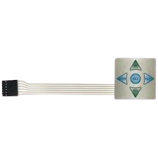
The 1x5 keypad membrane is a flexible and lightweight input device designed for user interaction in electronic systems. It consists of a single row of five buttons, each connected to conductive traces that register a button press when activated. This component is widely used in applications requiring simple and compact user input, such as control panels, home appliances, and embedded systems.

Explore Projects Built with 1x5 keypad membrane

Use Cirkit Designer to design, explore, and prototype these projects online. Some projects support real-time simulation. Click "Open Project" to start designing instantly!
Arduino UNO Keypad-Controlled LED and Buzzer System with RTC and Bluetooth
Image of Uni: A project utilizing 1x5 keypad membrane in a practical application
This circuit is an Arduino-based keypad interface system that reads input from a 4x4 membrane matrix keypad and displays the pressed key on the serial monitor. It also includes a real-time clock (RTC) module, a Bluetooth module, and visual indicators using red and green LEDs. Additionally, a buzzer is controlled via an NPN transistor for audio feedback.
Cirkit Designer LogoOpen Project in Cirkit Designer
Arduino Mega 2560-Based Smart Home Control System with LCD Display and Flame Sensor
Image of Copy of schoolproject (1): A project utilizing 1x5 keypad membrane in a practical application
This circuit is a multi-functional embedded system featuring an Arduino Mega 2560 microcontroller that interfaces with a 4x4 membrane keypad, a 20x4 I2C LCD, an 8x8 LED matrix, a DS3231 RTC module, a passive buzzer, and a KY-026 flame sensor. The system is powered by a 5V PSU and is designed to provide real-time clock functionality, user input via the keypad, visual output on the LCD and LED matrix, and flame detection with an audible alert.
Cirkit Designer LogoOpen Project in Cirkit Designer
Arduino UNO and ESP8266-Based Smart Lock with Keypad and LCD Display
Image of Lock: A project utilizing 1x5 keypad membrane in a practical application
This circuit is a security system that uses a 4x4 membrane keypad to input a PIN, which is processed by an Arduino UNO. Upon entering the correct PIN, the system activates a servo motor and a relay, and displays status messages on a 16x2 I2C LCD screen. Additionally, an ESP8266 module is included for potential wireless communication.
Cirkit Designer LogoOpen Project in Cirkit Designer
Wi-Fi Controlled Access System with ESP32, Keypad, and LCD Display
Image of tryyyyy: A project utilizing 1x5 keypad membrane in a practical application
This circuit is a Wi-Fi-enabled access control system using an ESP32 microcontroller, a 4x4 membrane keypad, and a 20x4 I2C LCD. The system allows users to enter a password via the keypad, which is verified by the ESP32; if correct, it activates a relay and displays the status on the LCD, while also providing web-based configuration and time synchronization via NTP.
Cirkit Designer LogoOpen Project in Cirkit Designer

Explore Projects Built with 1x5 keypad membrane

Use Cirkit Designer to design, explore, and prototype these projects online. Some projects support real-time simulation. Click "Open Project" to start designing instantly!
Image of Uni: A project utilizing 1x5 keypad membrane in a practical application
Arduino UNO Keypad-Controlled LED and Buzzer System with RTC and Bluetooth
This circuit is an Arduino-based keypad interface system that reads input from a 4x4 membrane matrix keypad and displays the pressed key on the serial monitor. It also includes a real-time clock (RTC) module, a Bluetooth module, and visual indicators using red and green LEDs. Additionally, a buzzer is controlled via an NPN transistor for audio feedback.
Cirkit Designer LogoOpen Project in Cirkit Designer
Image of Copy of schoolproject (1): A project utilizing 1x5 keypad membrane in a practical application
Arduino Mega 2560-Based Smart Home Control System with LCD Display and Flame Sensor
This circuit is a multi-functional embedded system featuring an Arduino Mega 2560 microcontroller that interfaces with a 4x4 membrane keypad, a 20x4 I2C LCD, an 8x8 LED matrix, a DS3231 RTC module, a passive buzzer, and a KY-026 flame sensor. The system is powered by a 5V PSU and is designed to provide real-time clock functionality, user input via the keypad, visual output on the LCD and LED matrix, and flame detection with an audible alert.
Cirkit Designer LogoOpen Project in Cirkit Designer
Image of Lock: A project utilizing 1x5 keypad membrane in a practical application
Arduino UNO and ESP8266-Based Smart Lock with Keypad and LCD Display
This circuit is a security system that uses a 4x4 membrane keypad to input a PIN, which is processed by an Arduino UNO. Upon entering the correct PIN, the system activates a servo motor and a relay, and displays status messages on a 16x2 I2C LCD screen. Additionally, an ESP8266 module is included for potential wireless communication.
Cirkit Designer LogoOpen Project in Cirkit Designer
Image of tryyyyy: A project utilizing 1x5 keypad membrane in a practical application
Wi-Fi Controlled Access System with ESP32, Keypad, and LCD Display
This circuit is a Wi-Fi-enabled access control system using an ESP32 microcontroller, a 4x4 membrane keypad, and a 20x4 I2C LCD. The system allows users to enter a password via the keypad, which is verified by the ESP32; if correct, it activates a relay and displays the status on the LCD, while also providing web-based configuration and time synchronization via NTP.
Cirkit Designer LogoOpen Project in Cirkit Designer

Common Applications and Use Cases

  • User input for microcontroller-based projects
  • Control panels for industrial or consumer devices
  • Menu navigation in embedded systems
  • Data entry in compact electronic devices
  • Prototyping and educational projects

Technical Specifications

The 1x5 keypad membrane is designed for ease of use and integration into electronic circuits. Below are its key technical details:

Key Technical Details

  • Number of Buttons: 5 (arranged in a single row)
  • Operating Voltage: 3.3V to 5V
  • Contact Resistance: < 100 ohms
  • Insulation Resistance: > 100M ohms at 100V DC
  • Operating Temperature Range: -20°C to +60°C
  • Connector Type: 5-pin ribbon cable with a female connector
  • Dimensions: Typically 70mm x 20mm (varies by manufacturer)
  • Lifespan: > 1,000,000 key presses

Pin Configuration and Descriptions

The 1x5 keypad membrane uses a 5-pin ribbon cable for connectivity. Each pin corresponds to a specific button or shared connection.

Pin Number Description Function
1 Button 1 Output Connects to the first button
2 Button 2 Output Connects to the second button
3 Button 3 Output Connects to the third button
4 Button 4 Output Connects to the fourth button
5 Button 5 Output Connects to the fifth button

Usage Instructions

The 1x5 keypad membrane is simple to use and can be directly interfaced with microcontrollers like the Arduino UNO. Below are the steps to integrate and use the keypad in a circuit:

Steps to Use the Keypad

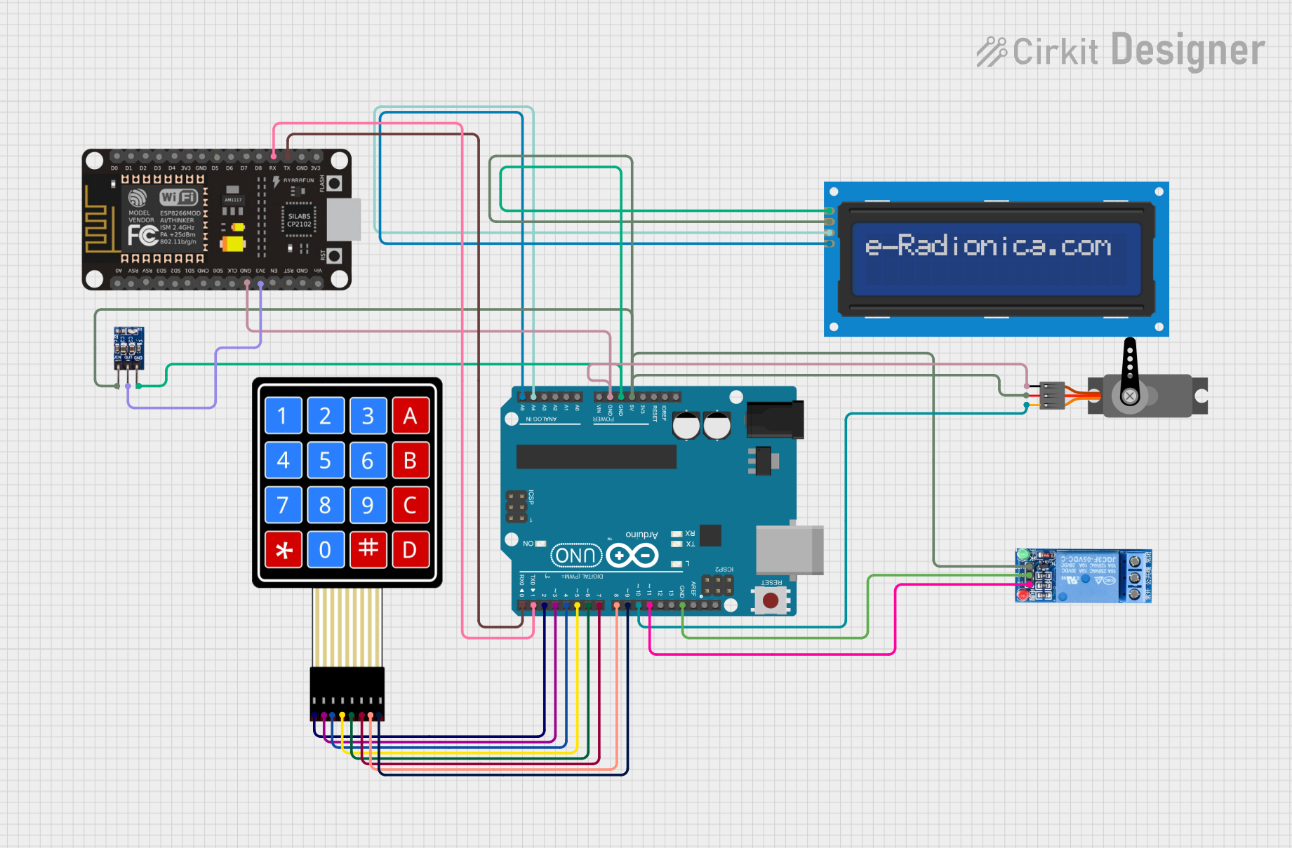
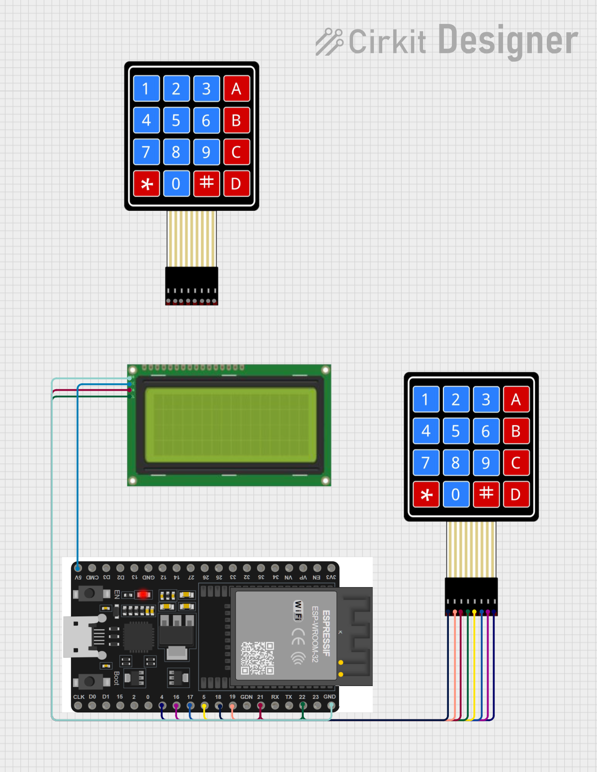
  1. Connect the Keypad to the Microcontroller:

    • Use jumper wires or a compatible connector to connect the 5-pin ribbon cable to the microcontroller's digital input pins.
    • Assign each pin of the keypad to a separate digital input pin on the microcontroller.
  2. Write the Code:

    • Use a microcontroller programming environment (e.g., Arduino IDE) to read the button states.
    • The buttons act as simple switches, so you can use digitalRead() to detect button presses.
  3. Debounce the Buttons:

    • Implement software debouncing to avoid false triggers caused by mechanical bouncing of the buttons.
  4. Test the Circuit:

    • Upload the code to the microcontroller and test each button to ensure proper functionality.

Example Code for Arduino UNO

Below is an example Arduino sketch to read the button states of a 1x5 keypad membrane:

// Define the pins connected to the keypad
const int buttonPins[5] = {2, 3, 4, 5, 6}; // Digital pins 2 to 6

void setup() {
  // Initialize serial communication for debugging
  Serial.begin(9600);

  // Set each button pin as an input with an internal pull-up resistor
  for (int i = 0; i < 5; i++) {
    pinMode(buttonPins[i], INPUT_PULLUP);
  }
}

void loop() {
  // Read and print the state of each button
  for (int i = 0; i < 5; i++) {
    int buttonState = digitalRead(buttonPins[i]);
    if (buttonState == LOW) { // Button is pressed (active low)
      Serial.print("Button ");
      Serial.print(i + 1);
      Serial.println(" is pressed");
    }
  }
  delay(100); // Small delay to reduce serial output clutter
}

Important Considerations and Best Practices

  • Pull-Up Resistors: Use internal pull-up resistors (or external ones if needed) to ensure stable readings.
  • Debouncing: Always implement debouncing in software to avoid erratic behavior.
  • Voltage Compatibility: Ensure the keypad's operating voltage matches the microcontroller's input voltage levels.
  • Connector Handling: Avoid excessive bending or pulling of the ribbon cable to prevent damage.

Troubleshooting and FAQs

Common Issues and Solutions

  1. Buttons Not Responding:

    • Cause: Loose or incorrect connections.
    • Solution: Double-check the wiring and ensure all connections are secure.
  2. Multiple Buttons Triggering Simultaneously:

    • Cause: Crosstalk or improper grounding.
    • Solution: Verify that each button pin is properly connected and isolated.
  3. Erratic Behavior or False Triggers:

    • Cause: Mechanical bouncing of the buttons.
    • Solution: Implement software debouncing in your code.
  4. Keypad Not Detected by Microcontroller:

    • Cause: Incorrect pin mapping in the code.
    • Solution: Verify that the pin numbers in the code match the actual connections.

FAQs

Q: Can I use the 1x5 keypad membrane with a 3.3V microcontroller?
A: Yes, the keypad is compatible with both 3.3V and 5V systems. Ensure the microcontroller's input pins can detect the voltage levels.

Q: How do I clean the keypad membrane?
A: Use a soft, dry cloth to clean the surface. Avoid using liquids or abrasive materials.

Q: Can I extend the ribbon cable?
A: Yes, but use shielded cables to minimize noise and signal degradation over longer distances.

Q: Is the keypad waterproof?
A: Most 1x5 keypad membranes are not waterproof. Check the manufacturer's specifications for water resistance ratings.

This concludes the documentation for the 1x5 keypad membrane.