How to Use Gas Sensor V2(Multichannel): Examples, Pinouts, and Specs
Introduction
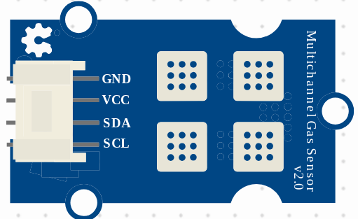
The Gas Sensor V2 (Multichannel), manufactured by Seeds (Part ID: V2), is a versatile and highly sensitive gas sensor designed to detect multiple gases simultaneously. It provides real-time data, making it an ideal choice for applications in air quality monitoring, industrial safety, and environmental research. Its multichannel capability allows it to measure various gas concentrations with high accuracy, ensuring reliable performance in diverse environments.
Explore Projects Built with Gas Sensor V2(Multichannel)
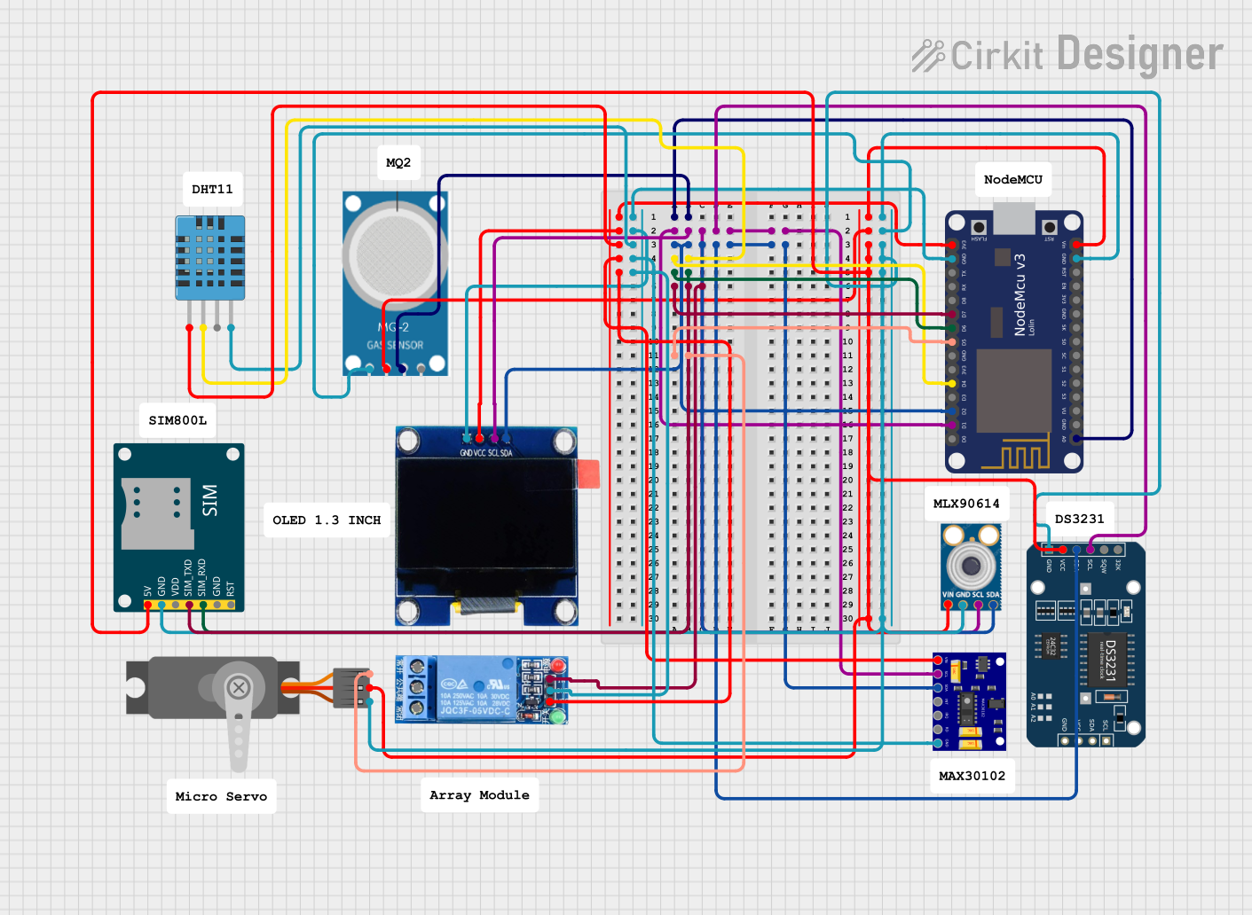
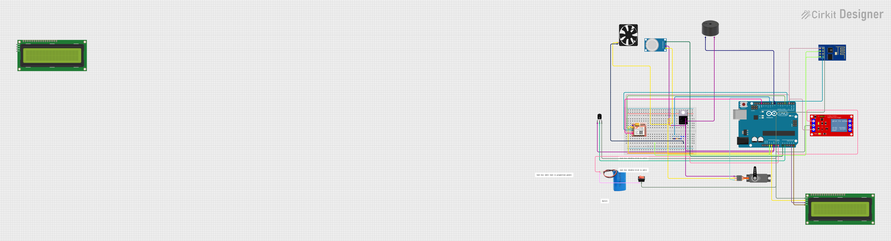
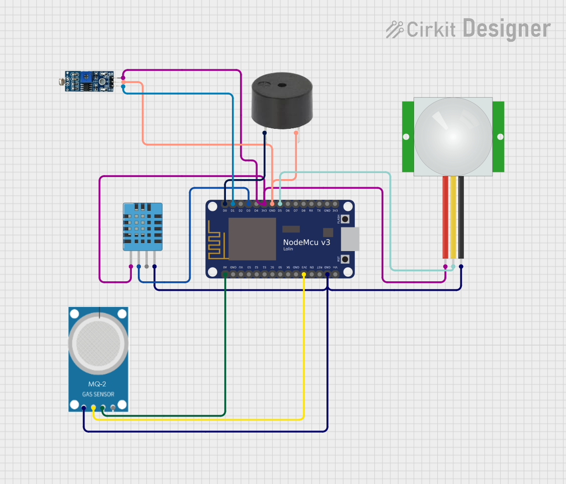
Explore Projects Built with Gas Sensor V2(Multichannel)
Common Applications
- Air Quality Monitoring: Detect pollutants and ensure compliance with environmental standards.
- Industrial Safety: Monitor hazardous gases in factories and workplaces.
- Environmental Research: Analyze gas concentrations for scientific studies.
- Smart Home Systems: Integrate into IoT devices for indoor air quality monitoring.
Technical Specifications
Key Technical Details
| Parameter | Value |
|---|---|
| Operating Voltage | 3.3V to 5V |
| Power Consumption | < 150mW |
| Detection Range | Varies by gas type (e.g., CO: 1-1000 ppm) |
| Response Time | < 30 seconds |
| Communication Interface | I2C, UART |
| Operating Temperature | -20°C to 50°C |
| Humidity Range | 15% to 90% RH (non-condensing) |
| Dimensions | 40mm x 20mm x 10mm |
Pin Configuration and Descriptions
| Pin Name | Pin Number | Description |
|---|---|---|
| VCC | 1 | Power supply input (3.3V to 5V) |
| GND | 2 | Ground connection |
| SDA | 3 | I2C data line |
| SCL | 4 | I2C clock line |
| TX | 5 | UART transmit pin |
| RX | 6 | UART receive pin |
| NC | 7 | Not connected (reserved for future use) |
Usage Instructions
How to Use the Component in a Circuit
- Power Supply: Connect the VCC pin to a 3.3V or 5V power source and the GND pin to ground.
- Communication Interface:
- For I2C communication, connect the SDA and SCL pins to the corresponding pins on your microcontroller.
- For UART communication, connect the TX and RX pins to the UART pins on your microcontroller.
- Pull-Up Resistors: If using I2C, ensure pull-up resistors (typically 4.7kΩ) are connected to the SDA and SCL lines.
- Gas Detection: Place the sensor in the environment to be monitored. Ensure it is not exposed to extreme temperatures or humidity.
Important Considerations and Best Practices
- Preheat Time: Allow the sensor to warm up for at least 2 minutes after powering on for accurate readings.
- Calibration: Periodically calibrate the sensor using a known gas concentration for precise measurements.
- Placement: Avoid placing the sensor in areas with high moisture or direct sunlight, as this may affect performance.
- Ventilation: Ensure proper airflow around the sensor for accurate gas detection.
Example Code for Arduino UNO
Below is an example of how to interface the Gas Sensor V2 with an Arduino UNO using the I2C protocol:
#include <Wire.h> // Include the Wire library for I2C communication

#define SENSOR_I2C_ADDRESS 0x50 // Replace with the sensor's I2C address

void setup() {
  Wire.begin(); // Initialize I2C communication
  Serial.begin(9600); // Start serial communication for debugging

  Serial.println("Gas Sensor V2 Initialization...");
}

void loop() {
  Wire.beginTransmission(SENSOR_I2C_ADDRESS); // Start communication with sensor
  Wire.write(0x01); // Example command to request gas concentration data
  Wire.endTransmission();

  delay(100); // Wait for the sensor to process the request

  Wire.requestFrom(SENSOR_I2C_ADDRESS, 2); // Request 2 bytes of data
  if (Wire.available() == 2) {
    int gasConcentration = Wire.read() << 8 | Wire.read(); // Combine two bytes
    Serial.print("Gas Concentration: ");
    Serial.print(gasConcentration);
    Serial.println(" ppm");
  } else {
    Serial.println("Error: No data received from sensor.");
  }

  delay(1000); // Wait 1 second before the next reading
}
Troubleshooting and FAQs
Common Issues and Solutions
No Data Received from Sensor
- Cause: Incorrect I2C address or wiring.
- Solution: Verify the sensor's I2C address and ensure proper connections to the SDA and SCL pins.
Inaccurate Readings
- Cause: Sensor not calibrated or insufficient preheat time.
- Solution: Calibrate the sensor using a known gas concentration and allow a 2-minute preheat time.
Sensor Not Responding
- Cause: Power supply issue or damaged sensor.
- Solution: Check the power supply voltage and ensure the sensor is not physically damaged.
Interference from Other Gases
- Cause: Cross-sensitivity to multiple gases.
- Solution: Use the sensor in a controlled environment or apply software filtering to isolate specific gas readings.
FAQs
Q: Can the sensor detect multiple gases simultaneously?
- A: Yes, the Gas Sensor V2 is designed to detect multiple gases and provide individual concentration readings.
Q: How often should the sensor be calibrated?
- A: Calibration frequency depends on usage, but it is recommended to calibrate every 6 months for optimal accuracy.
Q: Is the sensor compatible with 3.3V microcontrollers?
- A: Yes, the sensor operates on both 3.3V and 5V power supplies, making it compatible with a wide range of microcontrollers.
Q: Can the sensor be used outdoors?
- A: While the sensor can operate outdoors, it should be protected from direct sunlight, rain, and extreme humidity.
This documentation provides a comprehensive guide to using the Gas Sensor V2 (Multichannel). For further assistance, refer to the manufacturer's datasheet or contact Seeds support.