How to Use 4047 ic : Examples, Pinouts, and Specs
Introduction
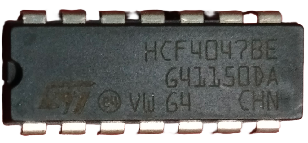
The 4047 IC is a versatile integrated circuit designed to operate as an astable multivibrator, monostable multivibrator, or Schmitt trigger. It is widely used in applications requiring precise timing, frequency generation, and pulse-width modulation. Its ability to operate in both monostable and astable modes makes it a popular choice for circuits such as oscillators, timers, and signal generators.
Explore Projects Built with 4047 ic

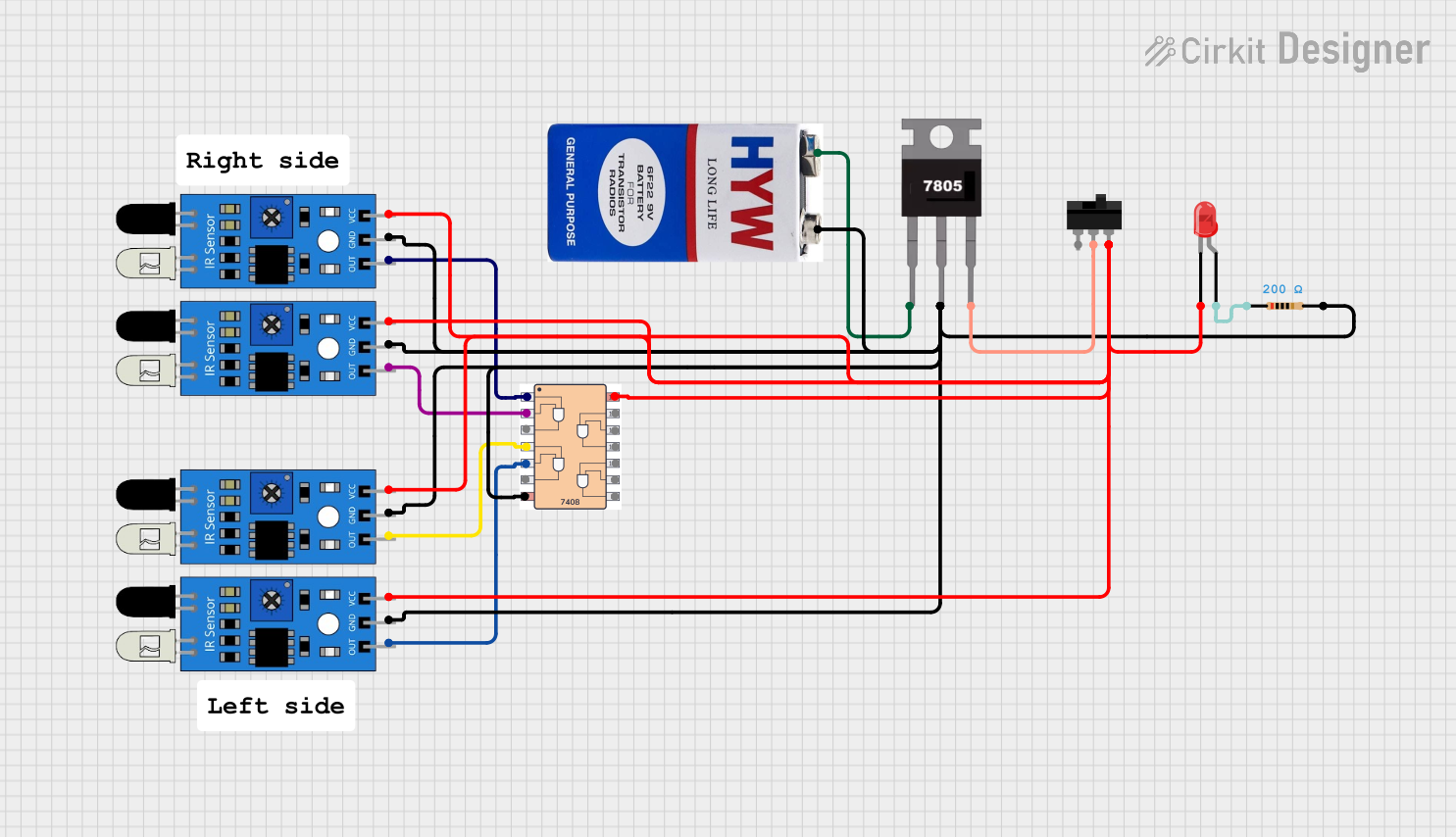


Explore Projects Built with 4047 ic
Common Applications
- Frequency generation for oscillators
- Pulse-width modulation (PWM) circuits
- Timer circuits (monostable mode)
- LED and lamp flashers
- Clock pulse generation
- Square wave generation
Technical Specifications
The 4047 IC is a CMOS-based device with low power consumption and high noise immunity. Below are its key technical details:
Key Specifications
- Supply Voltage (Vcc): 3V to 15V
- Operating Current: 10 µA (typical at 5V)
- Output Current: 3.2 mA (maximum at 5V)
- Frequency Range (Astable Mode): Up to 1 MHz
- Temperature Range: -40°C to +85°C
- Logic Compatibility: CMOS and TTL
- Package Types: DIP-14, SOIC-14
Pin Configuration and Descriptions
The 4047 IC comes in a 14-pin package. Below is the pinout and description:
| Pin Number | Pin Name | Description |
|---|---|---|
| 1 | Astable Input | External resistor connection for astable mode frequency control. |
| 2 | Astable Input | External capacitor connection for astable mode frequency control. |
| 3 | Astable/Monostable Select (A/!M) | Selects between astable (logic HIGH) and monostable (logic LOW) modes. |
| 4 | Reset | Resets the IC when logic HIGH is applied. |
| 5 | Trigger | Trigger input for monostable mode. |
| 6 | Output Q | Primary output of the IC. |
| 7 | Output !Q | Complementary output of the IC. |
| 8 | Ground (GND) | Ground connection. |
| 9 | External Capacitor | External capacitor connection for timing in monostable mode. |
| 10 | External Resistor | External resistor connection for timing in monostable mode. |
| 11 | Not Connected (NC) | No internal connection. |
| 12 | Vcc | Positive power supply. |
| 13 | Oscillator Output | Oscillator signal output in astable mode. |
| 14 | Discharge | Discharge pin for the external capacitor. |
Usage Instructions
Using the 4047 IC in a Circuit
The 4047 IC can be configured in two primary modes: astable and monostable. Below are the steps to use the IC in each mode:
1. Astable Mode (Oscillator Mode)
- Connect a resistor between Pin 1 and Pin 2, and a capacitor between Pin 2 and GND.
- Set Pin 3 (A/!M) to logic HIGH to enable astable mode.
- The frequency of oscillation is determined by the resistor (R) and capacitor (C) values: [ f = \frac{1}{4.4 \times R \times C} ]
- The output square wave is available at Pin 6 (Q) and its complement at Pin 7 (!Q).
2. Monostable Mode (Timer Mode)
- Connect a resistor between Pin 10 and Vcc, and a capacitor between Pin 9 and GND.
- Set Pin 3 (A/!M) to logic LOW to enable monostable mode.
- Apply a trigger pulse to Pin 5 to start the timing cycle.
- The pulse width is determined by the resistor (R) and capacitor (C) values: [ T = 2.48 \times R \times C ]
- The output pulse is available at Pin 6 (Q).
Important Considerations
- Ensure the supply voltage (Vcc) is within the specified range (3V to 15V).
- Use decoupling capacitors (e.g., 0.1 µF) near the power supply pins to reduce noise.
- Avoid leaving unused input pins floating; connect them to GND or Vcc as needed.
- For precise timing, use high-quality resistors and capacitors with low tolerance.
Example: Connecting the 4047 IC to an Arduino UNO
The 4047 IC can be used with an Arduino UNO to generate a square wave. Below is an example of how to configure the IC in astable mode and read the output using Arduino:
Circuit Connections
- Connect Pin 12 (Vcc) to the 5V pin of the Arduino.
- Connect Pin 8 (GND) to the GND pin of the Arduino.
- Connect a 10 kΩ resistor between Pin 1 and Pin 2.
- Connect a 0.1 µF capacitor between Pin 2 and GND.
- Set Pin 3 (A/!M) to HIGH (connect to 5V).
- Connect Pin 6 (Q) to a digital input pin on the Arduino (e.g., Pin 2).
Arduino Code
// Define the input pin for the 4047 IC output
const int inputPin = 2;

void setup() {
  pinMode(inputPin, INPUT); // Set the input pin as an input
  Serial.begin(9600);       // Initialize serial communication
}

void loop() {
  int state = digitalRead(inputPin); // Read the state of the 4047 output
  Serial.print("4047 Output State: ");
  Serial.println(state); // Print the state to the Serial Monitor
  delay(500);            // Wait for 500 ms before reading again
}
Troubleshooting and FAQs
Common Issues and Solutions
No Output Signal in Astable Mode
- Cause: Incorrect resistor or capacitor values.
- Solution: Verify the R and C values and ensure they are within the recommended range.
No Response in Monostable Mode
- Cause: Trigger pulse not applied or incorrect timing components.
- Solution: Ensure a proper trigger pulse is applied to Pin 5 and check the R and C values.
Output Signal is Unstable
- Cause: Noise or insufficient decoupling.
- Solution: Add a 0.1 µF decoupling capacitor near the Vcc and GND pins.
High Power Consumption
- Cause: Supply voltage too high or incorrect connections.
- Solution: Ensure the supply voltage is within the specified range (3V to 15V).
FAQs
Q1: Can the 4047 IC generate a sine wave?
A1: No, the 4047 IC generates square waves. For sine wave generation, additional circuitry is required.
Q2: What is the maximum frequency the 4047 IC can generate?
A2: The 4047 IC can generate frequencies up to 1 MHz in astable mode, depending on the R and C values.
Q3: Can I use the 4047 IC with a 3.3V power supply?
A3: Yes, the IC operates with supply voltages as low as 3V, making it compatible with 3.3V systems.
Q4: What happens if I leave the A/!M pin floating?
A4: Leaving the A/!M pin floating can cause unpredictable behavior. Always connect it to either Vcc (astable mode) or GND (monostable mode).