How to Use Wickv1: Examples, Pinouts, and Specs
Introduction
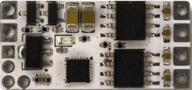
Wickv1, manufactured by Wicked (Part ID: v1), is a versatile electronic component designed to act as a connector or interface in electronic circuits. It facilitates the flow of current or signals between different parts of a system, making it an essential component in a wide range of applications. Its robust design and reliable performance make it suitable for both hobbyist projects and professional systems.
Explore Projects Built with Wickv1


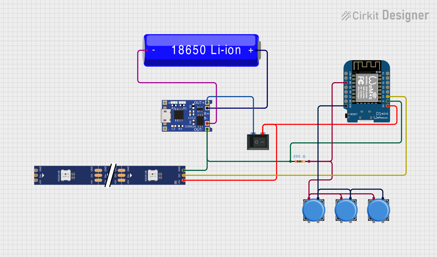

Explore Projects Built with Wickv1
Common Applications and Use Cases
- Signal Routing: Used to connect different modules or subsystems in a circuit.
- Power Distribution: Facilitates the transfer of power between components.
- Prototyping: Ideal for breadboard and PCB-based prototyping.
- IoT Devices: Commonly used in Internet of Things (IoT) applications for interfacing sensors and actuators.
- Embedded Systems: Acts as a reliable interface in microcontroller-based systems.
Technical Specifications
Below are the key technical details and pin configuration for the Wickv1 component:
Key Technical Details
| Parameter | Value |
|---|---|
| Manufacturer | Wicked |
| Part ID | v1 |
| Operating Voltage | 3.3V to 5V |
| Maximum Current | 1A |
| Operating Temperature | -40°C to 85°C |
| Connector Type | 4-pin interface |
| Dimensions | 10mm x 10mm x 5mm |
Pin Configuration and Descriptions
The Wickv1 component features a 4-pin interface. The pinout is described in the table below:
| Pin Number | Pin Name | Description |
|---|---|---|
| 1 | VCC | Power supply input (3.3V to 5V) |
| 2 | GND | Ground connection |
| 3 | SIGNAL_IN | Input signal pin for data or control signals |
| 4 | SIGNAL_OUT | Output signal pin for data or control signals |
Usage Instructions
How to Use the Wickv1 in a Circuit
- Power Connection: Connect the
VCCpin to a 3.3V or 5V power source and theGNDpin to the ground of your circuit. - Signal Input: Use the
SIGNAL_INpin to receive data or control signals from a microcontroller or other source. - Signal Output: The
SIGNAL_OUTpin can be used to send processed or relayed signals to another component or module. - Mounting: The compact size of the Wickv1 makes it easy to integrate into breadboards or solder onto PCBs.
Important Considerations and Best Practices
- Voltage Compatibility: Ensure the input voltage does not exceed the specified range (3.3V to 5V) to avoid damage.
- Current Limitations: Do not exceed the maximum current rating of 1A.
- Signal Integrity: Use short and shielded wires for signal connections to minimize noise and interference.
- Polarity: Double-check the polarity of the power supply to prevent reverse voltage damage.
Example: Using Wickv1 with an Arduino UNO
Below is an example of how to use the Wickv1 component with an Arduino UNO to transmit a signal:
// Example: Using Wickv1 to transmit a signal from Arduino UNO

const int signalOutPin = 3; // Arduino pin connected to Wickv1 SIGNAL_IN
const int signalInPin = 2;  // Arduino pin connected to Wickv1 SIGNAL_OUT

void setup() {
  pinMode(signalOutPin, OUTPUT); // Set SIGNAL_IN as output
  pinMode(signalInPin, INPUT);  // Set SIGNAL_OUT as input
}

void loop() {
  digitalWrite(signalOutPin, HIGH); // Send a HIGH signal to Wickv1
  delay(1000); // Wait for 1 second
  digitalWrite(signalOutPin, LOW);  // Send a LOW signal to Wickv1
  delay(1000); // Wait for 1 second

  // Read the signal from Wickv1 and print it to the Serial Monitor
  int receivedSignal = digitalRead(signalInPin);
  Serial.begin(9600);
  Serial.print("Received Signal: ");
  Serial.println(receivedSignal);
}
Troubleshooting and FAQs
Common Issues and Solutions
No Signal Transmission
- Cause: Incorrect wiring or loose connections.
- Solution: Verify all connections, especially the
SIGNAL_INandSIGNAL_OUTpins.
Component Overheating
- Cause: Exceeding the maximum current or voltage rating.
- Solution: Ensure the input voltage is within the 3.3V to 5V range and the current does not exceed 1A.
Signal Noise or Interference
- Cause: Long or unshielded wires.
- Solution: Use shorter wires and consider shielding to reduce noise.
Reverse Polarity Damage
- Cause: Power supply connected with incorrect polarity.
- Solution: Double-check the polarity of the power supply before connecting.
FAQs
Q1: Can Wickv1 handle analog signals?
A1: Yes, Wickv1 can handle both analog and digital signals, provided they are within the specified voltage range.
Q2: Is Wickv1 compatible with 12V systems?
A2: No, Wickv1 is designed for 3.3V to 5V systems. Using it with 12V may damage the component.
Q3: Can I use Wickv1 for high-frequency signals?
A3: Wickv1 is suitable for low to moderate frequency signals. For high-frequency applications, ensure proper shielding and impedance matching.
Q4: How do I mount Wickv1 on a PCB?
A4: Wickv1 can be soldered directly onto a PCB or used with a compatible socket for easy replacement.
By following this documentation, you can effectively integrate and troubleshoot the Wickv1 component in your projects.