How to Use Thermopile Infrared (IR) Sensor: Examples, Pinouts, and Specs

Introduction
The Thermometrics ZTP135SR is a thermopile infrared (IR) sensor designed to detect infrared radiation and convert it into an electrical signal. This enables non-contact temperature measurement and presence detection. The sensor is highly sensitive to infrared radiation, making it ideal for applications requiring accurate temperature readings without physical contact.
Explore Projects Built with Thermopile Infrared (IR) Sensor
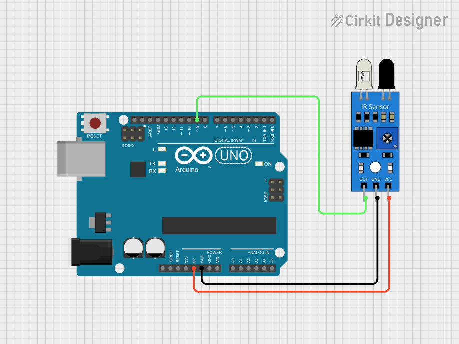
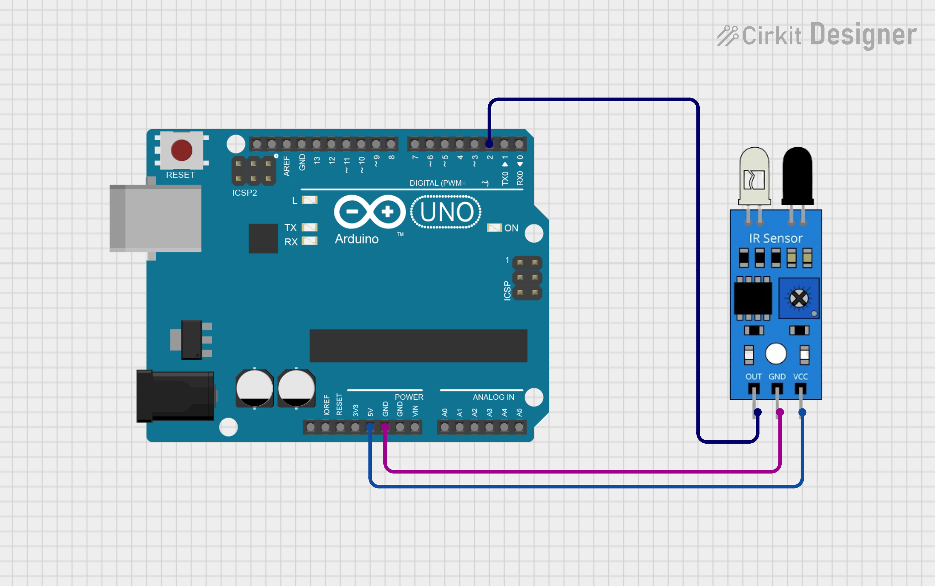
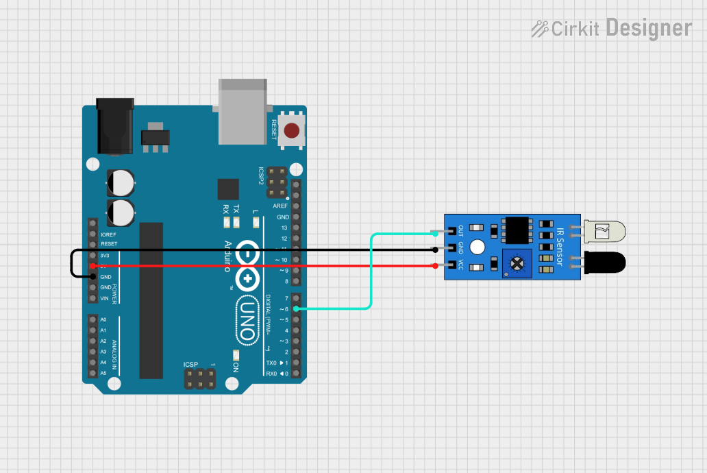
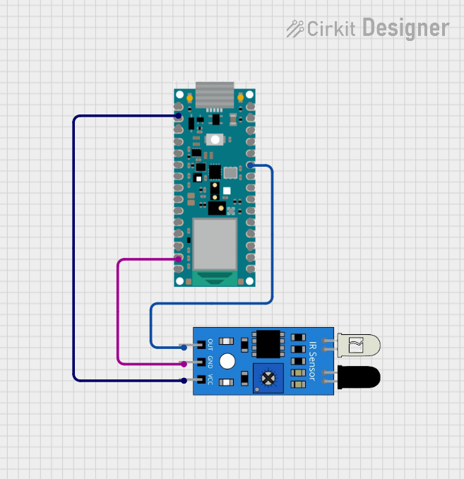
Explore Projects Built with Thermopile Infrared (IR) Sensor
Common Applications and Use Cases
- Non-contact temperature measurement (e.g., thermometers, HVAC systems)
- Human presence detection in smart home devices
- Industrial process monitoring
- Medical devices (e.g., ear and forehead thermometers)
- Consumer electronics (e.g., motion-activated devices)
Technical Specifications
The following table outlines the key technical details of the ZTP135SR thermopile IR sensor:
| Parameter | Value |
|---|---|
| Manufacturer | Thermometrics |
| Part Number | ZTP135SR |
| Operating Voltage | 2.7V to 5.5V |
| Output Signal | Analog voltage proportional to IR |
| Spectral Response Range | 2 µm to 22 µm |
| Field of View (FOV) | 90° |
| Operating Temperature Range | -10°C to +85°C |
| Storage Temperature Range | -20°C to +100°C |
| Package Type | TO-46 |
Pin Configuration and Descriptions
The ZTP135SR has a simple pinout configuration, as shown below:
| Pin Number | Pin Name | Description |
|---|---|---|
| 1 | VDD | Power supply input (2.7V to 5.5V) |
| 2 | OUT | Analog output signal proportional to IR radiation |
| 3 | GND | Ground connection |
Usage Instructions
How to Use the ZTP135SR in a Circuit
- Power Supply: Connect the VDD pin to a stable power source (2.7V to 5.5V) and the GND pin to the ground of the circuit.
- Signal Output: The OUT pin provides an analog voltage signal proportional to the detected infrared radiation. This signal can be read using an analog-to-digital converter (ADC) on a microcontroller.
- Placement: Ensure the sensor is positioned with a clear line of sight to the target object for accurate temperature measurement. Avoid obstructions or reflective surfaces that may interfere with the IR signal.
Important Considerations and Best Practices
- Calibration: For precise temperature measurements, calibrate the sensor using known temperature references.
- Ambient Temperature Compensation: Use an external temperature sensor to account for ambient temperature variations, as they can affect the accuracy of the ZTP135SR.
- Noise Filtering: Add a capacitor (e.g., 0.1 µF) between the VDD and GND pins to reduce power supply noise.
- Field of View: Ensure the target object is within the sensor's 90° field of view for optimal performance.
Example: Connecting the ZTP135SR to an Arduino UNO
Below is an example of how to connect and read data from the ZTP135SR using an Arduino UNO:
Circuit Diagram
- VDD → 5V pin on Arduino
- GND → GND pin on Arduino
- OUT → A0 (Analog Input) pin on Arduino
Arduino Code
// Thermopile IR Sensor (ZTP135SR) Example Code
// Reads the analog output from the sensor and converts it to a voltage value.

const int sensorPin = A0; // Analog pin connected to the OUT pin of ZTP135SR

void setup() {
  Serial.begin(9600); // Initialize serial communication at 9600 baud
  pinMode(sensorPin, INPUT); // Set the sensor pin as input
}

void loop() {
  int sensorValue = analogRead(sensorPin); // Read the analog value from the sensor
  float voltage = sensorValue * (5.0 / 1023.0); // Convert to voltage (5V reference)

  // Print the voltage value to the Serial Monitor
  Serial.print("Sensor Voltage: ");
  Serial.print(voltage);
  Serial.println(" V");

  delay(500); // Wait for 500ms before the next reading
}
Troubleshooting and FAQs
Common Issues and Solutions
No Output Signal
- Cause: Incorrect wiring or insufficient power supply.
- Solution: Verify the connections and ensure the power supply voltage is within the specified range (2.7V to 5.5V).
Inaccurate Temperature Readings
- Cause: Ambient temperature variations or improper calibration.
- Solution: Use an external temperature sensor for ambient compensation and calibrate the ZTP135SR with known temperature references.
Noisy Output Signal
- Cause: Power supply noise or electromagnetic interference.
- Solution: Add a decoupling capacitor (e.g., 0.1 µF) between the VDD and GND pins to filter noise.
Sensor Overheating
- Cause: Operating the sensor beyond its temperature range.
- Solution: Ensure the sensor is used within the specified operating temperature range (-10°C to +85°C).
FAQs
Q1: Can the ZTP135SR detect human presence?
A1: Yes, the ZTP135SR can detect human presence by sensing the infrared radiation emitted by the human body.
Q2: What is the maximum distance for temperature measurement?
A2: The effective distance depends on the size of the target object and its infrared emission. For small objects, the sensor should be placed closer for accurate readings.
Q3: Can I use the ZTP135SR with a 3.3V microcontroller?
A3: Yes, the ZTP135SR operates within a voltage range of 2.7V to 5.5V, making it compatible with 3.3V systems.
Q4: Does the sensor require additional components for operation?
A4: While the sensor can operate standalone, adding a decoupling capacitor and an ambient temperature sensor can improve performance and accuracy.