How to Use RP4M V1.2: Examples, Pinouts, and Specs
Introduction
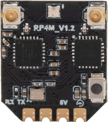
The RP4M V1.2, manufactured by Radio Master (Part ID: RP4M_V1.2), is a versatile microcontroller board designed for rapid prototyping and development. It is equipped with multiple input/output pins, supports a wide range of sensors and modules, and is compatible with popular programming environments such as Arduino IDE and MicroPython. This makes it an excellent choice for both hobbyists and professionals working on IoT, robotics, and embedded systems projects.
Explore Projects Built with RP4M V1.2


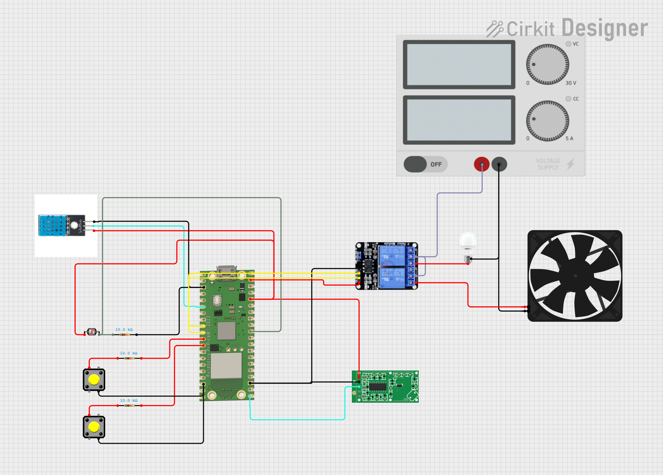
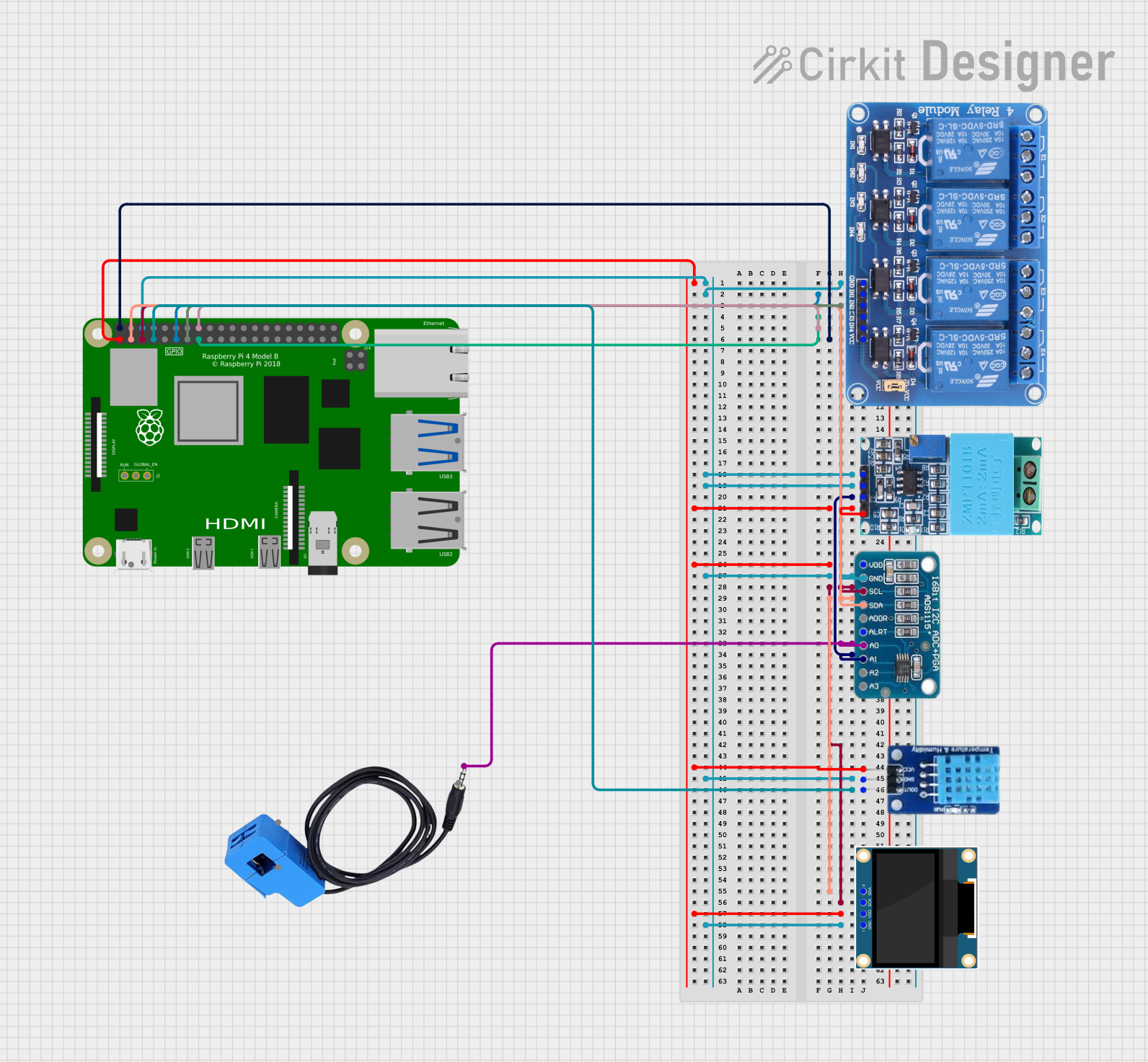
Explore Projects Built with RP4M V1.2
Common Applications and Use Cases
- IoT (Internet of Things) devices and smart home automation
- Robotics and motor control systems
- Sensor data acquisition and processing
- Educational projects and prototyping
- Wearable technology and portable devices
Technical Specifications
The RP4M V1.2 is built to provide flexibility and performance for a variety of applications. Below are its key technical details:
Key Technical Details
| Parameter | Specification |
|---|---|
| Microcontroller | ARM Cortex-M4-based processor |
| Operating Voltage | 3.3V |
| Input Voltage (VIN) | 5V to 12V |
| Digital I/O Pins | 20 (including PWM support on 8 pins) |
| Analog Input Pins | 6 |
| Communication Interfaces | UART, I2C, SPI |
| Flash Memory | 256 KB |
| SRAM | 64 KB |
| Clock Speed | 48 MHz |
| USB Interface | Micro-USB (for programming and power) |
| Dimensions | 50mm x 25mm |
Pin Configuration and Descriptions
The RP4M V1.2 features a total of 26 pins, including power, digital, and analog pins. Below is the pinout description:
| Pin Number | Pin Name | Description |
|---|---|---|
| 1 | VIN | Input voltage (5V to 12V) |
| 2 | GND | Ground |
| 3 | 3.3V | 3.3V output for powering peripherals |
| 4-13 | D0-D9 | Digital I/O pins (D3-D10 support PWM) |
| 14-19 | A0-A5 | Analog input pins (10-bit resolution) |
| 20 | SDA | I2C Data Line |
| 21 | SCL | I2C Clock Line |
| 22 | TX | UART Transmit |
| 23 | RX | UART Receive |
| 24 | MOSI | SPI Master Out Slave In |
| 25 | MISO | SPI Master In Slave Out |
| 26 | SCK | SPI Clock |
Usage Instructions
The RP4M V1.2 is designed to be user-friendly and compatible with popular development environments. Below are the steps and best practices for using the board:
How to Use the RP4M V1.2 in a Circuit
Powering the Board:
- Connect the board to a power source using the Micro-USB port or the VIN pin (5V to 12V).
- Ensure the power supply is stable to avoid damage to the board.
Connecting Peripherals:
- Use the digital pins (D0-D9) for digital sensors, actuators, or modules.
- Connect analog sensors to the analog input pins (A0-A5).
- For communication modules, use the UART (TX/RX), I2C (SDA/SCL), or SPI (MOSI/MISO/SCK) interfaces.
Programming the Board:
- Install the Arduino IDE or another compatible environment.
- Select the appropriate board and port from the IDE settings.
- Write your code and upload it to the board via the Micro-USB connection.
Important Considerations and Best Practices
- Always check the voltage and current requirements of connected peripherals to avoid overloading the board.
- Use pull-up or pull-down resistors for stable digital input signals.
- Avoid connecting the board to power sources exceeding the specified voltage range (5V to 12V).
- Use decoupling capacitors for noise-sensitive applications.
Example Code for Arduino UNO Compatibility
The RP4M V1.2 can be programmed using the Arduino IDE. Below is an example code to read an analog sensor and control an LED:
// Define pin connections
const int analogPin = A0; // Analog sensor connected to A0
const int ledPin = D3;    // LED connected to digital pin D3

void setup() {
  pinMode(ledPin, OUTPUT); // Set LED pin as output
  Serial.begin(9600);      // Initialize serial communication
}

void loop() {
  int sensorValue = analogRead(analogPin); // Read analog sensor value
  Serial.println(sensorValue);            // Print value to Serial Monitor

  // Map sensor value to PWM range (0-255) and write to LED
  int ledBrightness = map(sensorValue, 0, 1023, 0, 255);
  analogWrite(ledPin, ledBrightness);

  delay(100); // Delay for stability
}
Troubleshooting and FAQs
Common Issues and Solutions
Board Not Detected by Computer:
- Ensure the USB cable is functional and supports data transfer.
- Check if the correct board and port are selected in the IDE.
- Install or update the necessary drivers for the RP4M V1.2.
Program Upload Fails:
- Verify that no other application is using the COM port.
- Press the reset button on the board before uploading the code.
- Check for syntax errors or incompatible libraries in the code.
Peripheral Not Responding:
- Double-check the wiring and pin connections.
- Ensure the peripheral is powered and compatible with the board's voltage levels.
- Use a multimeter to verify signal integrity.
FAQs
Q: Can the RP4M V1.2 be powered by a battery?
A: Yes, the board can be powered using a battery connected to the VIN and GND pins, as long as the voltage is within the 5V to 12V range.
Q: Is the RP4M V1.2 compatible with Arduino libraries?
A: Yes, the board is fully compatible with most Arduino libraries and can be programmed using the Arduino IDE.
Q: What is the maximum current output of the 3.3V pin?
A: The 3.3V pin can supply up to 50mA, which is sufficient for low-power peripherals.
Q: Can I use the RP4M V1.2 for wireless communication?
A: Yes, you can connect wireless modules such as Wi-Fi or Bluetooth via the UART, I2C, or SPI interfaces.
By following this documentation, users can effectively utilize the RP4M V1.2 for a wide range of applications.