
How to Use LM 358 Dual Op-Amp: Examples, Pinouts, and Specs
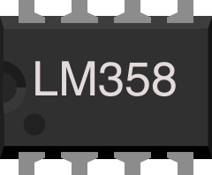
 Design with LM 358 Dual Op-Amp in Cirkit Designer
Introduction
The LM358 is a dual operational amplifier (op-amp) manufactured by Texas Instruments. It is designed to operate on a single power supply, making it highly versatile for a wide range of applications. The LM358 is commonly used for signal conditioning, filtering, and amplification in analog circuits. Its low power consumption and ability to function with a single supply voltage make it ideal for battery-powered devices and other low-power applications.
Explore Projects Built with LM 358 Dual Op-Amp
 Open Project in Cirkit Designer
 Open Project in Cirkit Designer
 Open Project in Cirkit Designer
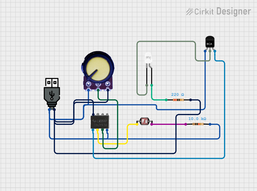 Open Project in Cirkit Designer
Explore Projects Built with LM 358 Dual Op-Amp
Open Project in Cirkit DesignerOpen Project in Cirkit DesignerOpen Project in Cirkit DesignerOpen Project in Cirkit DesignerCommon Applications
- Signal amplification in sensor circuits
- Active filters (low-pass, high-pass, band-pass)
- Voltage followers (buffer circuits)
- Comparators
- Oscillators and waveform generators
- Analog computation circuits
Technical Specifications
The LM358 is a robust and reliable component with the following key specifications:
| Parameter | Value |
|---|---|
| Supply Voltage Range | 3V to 32V (single supply) |
| Input Voltage Range | 0V to (V+ - 1.5V) |
| Output Voltage Swing | 0V to (V+ - 1.5V) |
| Supply Current (per op-amp) | 0.5 mA (typical) |
| Gain Bandwidth Product | 1 MHz |
| Slew Rate | 0.3 V/µs |
| Operating Temperature Range | 0°C to 70°C |
| Package Types | DIP-8, SOIC-8, TSSOP-8 |
Pin Configuration and Descriptions
The LM358 is available in an 8-pin package. Below is the pinout and description:
| Pin Number | Pin Name | Description |
|---|---|---|
| 1 | OUT1 | Output of Op-Amp 1 |
| 2 | IN1- | Inverting Input of Op-Amp 1 |
| 3 | IN1+ | Non-Inverting Input of Op-Amp 1 |
| 4 | V- (GND) | Negative Power Supply or Ground |
| 5 | IN2+ | Non-Inverting Input of Op-Amp 2 |
| 6 | IN2- | Inverting Input of Op-Amp 2 |
| 7 | OUT2 | Output of Op-Amp 2 |
| 8 | V+ | Positive Power Supply |
Usage Instructions
The LM358 is straightforward to use in a variety of circuits. Below are the steps and considerations for integrating it into your design:
Basic Circuit Configuration
- Power Supply: Connect the positive supply voltage (V+) to pin 8 and the ground (V-) to pin 4. The LM358 can operate with a single supply (e.g., 5V or 12V) or a dual supply (e.g., ±15V).
- Input Connections: Connect the signal to be amplified to the non-inverting input (IN+) or inverting input (IN-), depending on the desired configuration.
- Output: The amplified signal will be available at the corresponding output pin (OUT1 or OUT2).
Important Considerations
- Input Voltage Range: Ensure the input voltage does not exceed the specified range (0V to V+ - 1.5V).
- Output Voltage Swing: The output cannot reach the full supply voltage range. Design your circuit accordingly.
- Bypass Capacitor: Place a decoupling capacitor (e.g., 0.1 µF) close to the power supply pins to reduce noise.
- Load Resistance: Avoid connecting very low resistance loads directly to the output, as this may cause distortion or instability.
Example: Using LM358 with Arduino UNO
The LM358 can be used with an Arduino UNO for signal amplification. Below is an example of amplifying a sensor signal:
Circuit Setup
- Connect the sensor output to the non-inverting input (IN1+).
- Use a resistor and capacitor network to set the gain and filter noise.
- Connect the output (OUT1) to an analog input pin on the Arduino.
Arduino Code
// Example code for reading an amplified signal from LM358
const int analogPin = A0; // Analog pin connected to LM358 output
int sensorValue = 0;      // Variable to store the sensor reading

void setup() {
  Serial.begin(9600); // Initialize serial communication
}

void loop() {
  sensorValue = analogRead(analogPin); // Read the amplified signal
  float voltage = sensorValue * (5.0 / 1023.0); // Convert to voltage
  Serial.print("Sensor Voltage: ");
  Serial.println(voltage); // Print the voltage to the Serial Monitor
  delay(500); // Wait for 500ms before the next reading
}
Best Practices
- Use proper grounding techniques to minimize noise.
- Avoid exceeding the maximum supply voltage to prevent damage.
- For high-frequency applications, consider the gain-bandwidth product and slew rate limitations.
Troubleshooting and FAQs
Common Issues
No Output Signal:
- Check the power supply connections (V+ and V-).
- Verify that the input signal is within the specified range.
- Ensure the load resistance is not too low.
Distorted Output:
- Verify that the output is not being driven beyond its voltage swing limits.
- Check for proper decoupling of the power supply.
Excessive Noise:
- Add bypass capacitors near the power supply pins.
- Use shielded cables for input signals.
Overheating:
- Ensure the supply voltage does not exceed the maximum rating.
- Check for short circuits in the output.
FAQs
Q: Can the LM358 operate with a dual power supply?
A: Yes, the LM358 can operate with a dual supply (e.g., ±15V) or a single supply (e.g., 5V or 12V).
Q: What is the maximum gain I can achieve with the LM358?
A: The gain depends on the external resistor configuration. However, the gain-bandwidth product is 1 MHz, so higher gains will reduce the bandwidth.
Q: Can I use the LM358 for audio applications?
A: While the LM358 can be used for basic audio amplification, its low slew rate (0.3 V/µs) may cause distortion in high-frequency audio signals.
Q: Is the LM358 suitable for battery-powered devices?
A: Yes, the LM358's low power consumption makes it ideal for battery-powered applications.