Cirkit Designer Logo
Cirkit Designer
Your all-in-one circuit design IDE
Home / 
Component Documentation

How to Use 433 MHz RF Receiver Module: Examples, Pinouts, and Specs

Image of 433 MHz RF Receiver Module
Cirkit Designer LogoDesign with 433 MHz RF Receiver Module in Cirkit Designer

Introduction

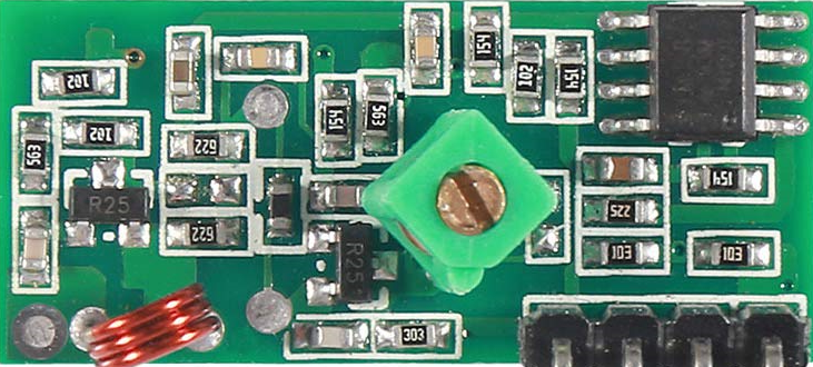
The 433 MHz RF Receiver Module is a compact and low-cost module capable of receiving radio frequency (RF) signals at the 433 MHz frequency band. This frequency band is widely used for a variety of wireless communication applications, including remote control systems, home automation, and telemetry. Due to its ease of use and broad range, it is a popular choice for hobbyists and professionals working on wireless projects.

Explore Projects Built with 433 MHz RF Receiver Module

Use Cirkit Designer to design, explore, and prototype these projects online. Some projects support real-time simulation. Click "Open Project" to start designing instantly!
433 MHz RF Transmitter and Receiver with Arduino UNO for Wireless Communication
Image of Wireless Communication: A project utilizing 433 MHz RF Receiver Module in a practical application
This circuit consists of two Arduino UNO microcontrollers, each connected to an RF 433 MHz Transmitter and a 433 MHz RF Receiver Module. The setup allows for wireless communication between the two Arduinos, enabling them to send and receive data over a 433 MHz RF link.
Cirkit Designer LogoOpen Project in Cirkit Designer
Arduino UNO with 433MHz RF Module for Wireless Communication
Image of Receiver: A project utilizing 433 MHz RF Receiver Module in a practical application
This circuit consists of an Arduino UNO connected to an RXN433MHz radio frequency module. The Arduino provides 5V power and ground to the RF module and is configured to communicate with it via digital pin D11. Additionally, a multimeter is connected with alligator clip cables to measure the voltage supplied to the RF module.
Cirkit Designer LogoOpen Project in Cirkit Designer
433 MHz RF Transmitter and Receiver with Arduino Uno for Wireless LED Control
Image of rf module up: A project utilizing 433 MHz RF Receiver Module in a practical application
This circuit consists of two Arduino Uno R3 microcontrollers communicating wirelessly using 433 MHz RF modules. One Arduino is connected to an RF transmitter to send data, while the other Arduino is connected to an RF receiver to receive data and control an LED based on the received signal.
Cirkit Designer LogoOpen Project in Cirkit Designer
ESP32-Based RF Communication System with 433 MHz Modules
Image of 433 mhz: A project utilizing 433 MHz RF Receiver Module in a practical application
This circuit comprises an ESP32 microcontroller connected to a 433 MHz RF transmitter and receiver pair. The ESP32 is programmed to receive and decode RF signals through the receiver module, as well as send RF signals via the transmitter module. Additionally, the ESP32 can communicate with a Bluetooth device to exchange commands and data, and it uses an LED for status indication.
Cirkit Designer LogoOpen Project in Cirkit Designer

Explore Projects Built with 433 MHz RF Receiver Module

Use Cirkit Designer to design, explore, and prototype these projects online. Some projects support real-time simulation. Click "Open Project" to start designing instantly!
Image of Wireless Communication: A project utilizing 433 MHz RF Receiver Module in a practical application
433 MHz RF Transmitter and Receiver with Arduino UNO for Wireless Communication
This circuit consists of two Arduino UNO microcontrollers, each connected to an RF 433 MHz Transmitter and a 433 MHz RF Receiver Module. The setup allows for wireless communication between the two Arduinos, enabling them to send and receive data over a 433 MHz RF link.
Cirkit Designer LogoOpen Project in Cirkit Designer
Image of Receiver: A project utilizing 433 MHz RF Receiver Module in a practical application
Arduino UNO with 433MHz RF Module for Wireless Communication
This circuit consists of an Arduino UNO connected to an RXN433MHz radio frequency module. The Arduino provides 5V power and ground to the RF module and is configured to communicate with it via digital pin D11. Additionally, a multimeter is connected with alligator clip cables to measure the voltage supplied to the RF module.
Cirkit Designer LogoOpen Project in Cirkit Designer
Image of rf module up: A project utilizing 433 MHz RF Receiver Module in a practical application
433 MHz RF Transmitter and Receiver with Arduino Uno for Wireless LED Control
This circuit consists of two Arduino Uno R3 microcontrollers communicating wirelessly using 433 MHz RF modules. One Arduino is connected to an RF transmitter to send data, while the other Arduino is connected to an RF receiver to receive data and control an LED based on the received signal.
Cirkit Designer LogoOpen Project in Cirkit Designer
Image of 433 mhz: A project utilizing 433 MHz RF Receiver Module in a practical application
ESP32-Based RF Communication System with 433 MHz Modules
This circuit comprises an ESP32 microcontroller connected to a 433 MHz RF transmitter and receiver pair. The ESP32 is programmed to receive and decode RF signals through the receiver module, as well as send RF signals via the transmitter module. Additionally, the ESP32 can communicate with a Bluetooth device to exchange commands and data, and it uses an LED for status indication.
Cirkit Designer LogoOpen Project in Cirkit Designer

Common Applications and Use Cases

  • Remote control for garage doors, gates, and home appliances
  • Wireless sensor networks
  • Home automation systems
  • DIY electronics projects
  • Telemetry and remote measurement systems

Technical Specifications

Key Technical Details

  • Operating Frequency: 433.92 MHz
  • Modulation: ASK (Amplitude Shift Keying)
  • Sensitivity: -105 dBm
  • Operating Voltage: 5V DC
  • Current Consumption: 3.5 mA (typical at 5V)
  • Operating Temperature: -10°C to +70°C

Pin Configuration and Descriptions

Pin Number Pin Name Description
1 VCC Power supply (5V DC)
2 DATA Data output pin
3 GND Ground connection
4 ANT Antenna connection (optional)

Usage Instructions

How to Use the Component in a Circuit

  1. Connect the VCC pin to a 5V power supply.
  2. Connect the GND pin to the ground of the power supply.
  3. The DATA pin outputs the demodulated data signal, which can be connected to a microcontroller for decoding.
  4. For optimal reception, connect a 17.3 cm wire to the ANT pin as an antenna (quarter wavelength at 433 MHz).

Important Considerations and Best Practices

  • Ensure a stable 5V power supply to avoid signal distortion.
  • Place the antenna in an upright position for better signal reception.
  • Avoid placing the module near metal objects or electronic devices that may cause interference.
  • Use proper encoding and decoding techniques to prevent interference from other RF devices.

Example Code for Arduino UNO

#include <RH_ASK.h>
#include <SPI.h> // Not required, but included for compatibility

// Create ASK object
RH_ASK rf_receiver(2000, 11, 12, 0, true);

void setup()
{
    Serial.begin(9600); // Start serial communication at 9600 baud
    if (!rf_receiver.init())
        Serial.println("init failed");
}

void loop()
{
    uint8_t buf[RH_ASK_MAX_MESSAGE_LEN];
    uint8_t buflen = sizeof(buf);

    // Check if received packet is available
    if (rf_receiver.recv(buf, &buflen))
    {
        // Print received message to serial
        Serial.print("Message Received: ");
        Serial.println((char*)buf);
    }
}
  • This example uses the RadioHead library to simplify RF communication.
  • The RH_ASK object is initialized with a bitrate of 2000 bps and RX pin on Arduino pin 11.
  • The init() function sets up the RF receiver; if it fails, an error message is printed.
  • In the loop(), the recv() method checks for a new message and prints it to the serial monitor.

Troubleshooting and FAQs

Common Issues Users Might Face

  • No data received: Ensure the antenna is properly connected and there is no interference from other devices.
  • Intermittent reception: Check for loose connections and ensure the power supply is stable.
  • Garbled data: Verify that the transmitter and receiver are using the same modulation and encoding schemes.

Solutions and Tips for Troubleshooting

  • Always perform a range test to determine the effective distance of your setup.
  • Use a spectrum analyzer to check for interference in the 433 MHz band.
  • Ensure that the baud rate of the serial communication matches the rate set in the Arduino sketch.

FAQs

Q: Can I use multiple RF receiver modules in the same area? A: Yes, but make sure each pair of transmitter and receiver operates on a different frequency or uses a unique encoding scheme to avoid interference.

Q: What is the range of the 433 MHz RF Receiver Module? A: The range can vary from a few meters to over 100 meters, depending on the transmitter power, antenna, and environmental conditions.

Q: Is it legal to use the 433 MHz band for wireless communication? A: The 433 MHz band is an ISM (Industrial, Scientific, and Medical) band and is generally license-free in many countries. However, users should check local regulations as there may be restrictions on power output or duty cycle.