How to Use 1.5" In OLED Display Module: Examples, Pinouts, and Specs
Introduction
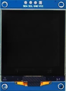
The 1.5" In OLED Display Module is a compact organic light-emitting diode display designed for high-contrast and vibrant color output. This module is ideal for applications requiring clear and sharp visuals, such as wearable devices, IoT projects, and portable electronics. Its low power consumption and wide viewing angles make it a popular choice for both hobbyists and professionals.
Explore Projects Built with 1.5" In OLED Display Module


Explore Projects Built with 1.5" In OLED Display Module
Common Applications
- Wearable devices (e.g., smartwatches, fitness trackers)
- IoT dashboards and status displays
- Portable measurement tools
- Embedded systems requiring graphical interfaces
- Arduino and Raspberry Pi projects
Technical Specifications
Below are the key technical details of the 1.5" In OLED Display Module:
| Parameter | Specification |
|---|---|
| Display Type | OLED (Organic Light-Emitting Diode) |
| Screen Size | 1.5 inches |
| Resolution | 128 x 128 pixels |
| Color Depth | 16-bit (65,536 colors) |
| Interface | SPI/I2C |
| Operating Voltage | 3.3V to 5V |
| Operating Current | ~20mA (typical) |
| Viewing Angle | >160° |
| Operating Temperature | -40°C to +85°C |
| Dimensions | 35mm x 35mm x 4mm |
Pin Configuration
The module typically has a 7-pin interface. Below is the pinout description:
| Pin | Name | Description |
|---|---|---|
| 1 | GND | Ground connection |
| 2 | VCC | Power supply (3.3V to 5V) |
| 3 | SCL | Serial Clock Line (SPI/I2C clock input) |
| 4 | SDA | Serial Data Line (SPI/I2C data input) |
| 5 | RES | Reset pin (active low) |
| 6 | DC | Data/Command control pin (high for data, low for command) |
| 7 | CS | Chip Select (active low, used in SPI mode) |
Usage Instructions
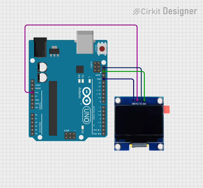
Connecting the Module
- Power Supply: Connect the
VCCpin to a 3.3V or 5V power source and theGNDpin to ground. - Communication Interface:
- For SPI: Connect
SCL,SDA,RES,DC, andCSto the corresponding pins on your microcontroller. - For I2C: Connect
SCLandSDAto the I2C pins of your microcontroller. Ensure proper pull-up resistors are used if required.
- For SPI: Connect
- Initialization: Use a compatible library (e.g., Adafruit SSD1351 for Arduino) to initialize and control the display.
Example Code for Arduino UNO
Below is an example of how to use the 1.5" In OLED Display Module with an Arduino UNO in SPI mode:
#include <Adafruit_GFX.h>      // Core graphics library
#include <Adafruit_SSD1351.h>  // OLED driver library

// Pin definitions for SPI connection
#define OLED_CS   10  // Chip Select pin
#define OLED_DC    9  // Data/Command pin
#define OLED_RST   8  // Reset pin

// Create an instance of the display object
Adafruit_SSD1351 display = Adafruit_SSD1351(128, 128, OLED_CS, OLED_DC, OLED_RST);

void setup() {
  // Initialize the display
  display.begin();

  // Clear the screen with a black background
  display.fillScreen(SSD1351_BLACK);

  // Display a message
  display.setTextColor(SSD1351_WHITE);  // Set text color to white
  display.setTextSize(2);              // Set text size
  display.setCursor(0, 0);             // Set cursor position
  display.println("Hello, OLED!");     // Print text to the display
}

void loop() {
  // Add any additional functionality here
}
Best Practices
- Ensure the power supply voltage matches the module's requirements (3.3V or 5V).
- Use level shifters if your microcontroller operates at 5V logic and the OLED module is 3.3V.
- Avoid prolonged display of static images to prevent burn-in.
- Use libraries like Adafruit GFX and SSD1351 for easier control and rendering.
Troubleshooting and FAQs
Common Issues
No Display Output:
- Verify all connections, especially
VCCandGND. - Ensure the correct communication interface (SPI/I2C) is selected in your code.
- Check if the
RESpin is properly connected and initialized.
- Verify all connections, especially
Flickering or Unstable Display:
- Ensure a stable power supply with sufficient current.
- Check for loose or poor-quality connections.
Incorrect Colors or Artifacts:
- Verify that the correct driver library (e.g., SSD1351) is being used.
- Ensure the display resolution and color depth are properly configured in the code.
FAQs
Q: Can I use this module with a Raspberry Pi?
A: Yes, the module is compatible with Raspberry Pi. Use the SPI or I2C interface and install the appropriate libraries (e.g., Luma.OLED).
Q: Does the module support grayscale?
A: No, this module supports 16-bit color depth, which provides 65,536 colors.
Q: How do I prevent burn-in on the OLED display?
A: Avoid displaying static images for extended periods. Use screen savers or periodically refresh the display content.
Q: Can I power the module directly from an Arduino UNO?
A: Yes, the module can be powered from the 5V pin of the Arduino UNO, but ensure the current draw does not exceed the Arduino's limits.