Cirkit Designer Logo
Cirkit Designer
Your all-in-one circuit design IDE
Home / 
Component Documentation

How to Use Adafruit I2C+SPI LCD Backpack: Examples, Pinouts, and Specs

Image of Adafruit I2C+SPI LCD Backpack
Cirkit Designer LogoDesign with Adafruit I2C+SPI LCD Backpack in Cirkit Designer

Introduction

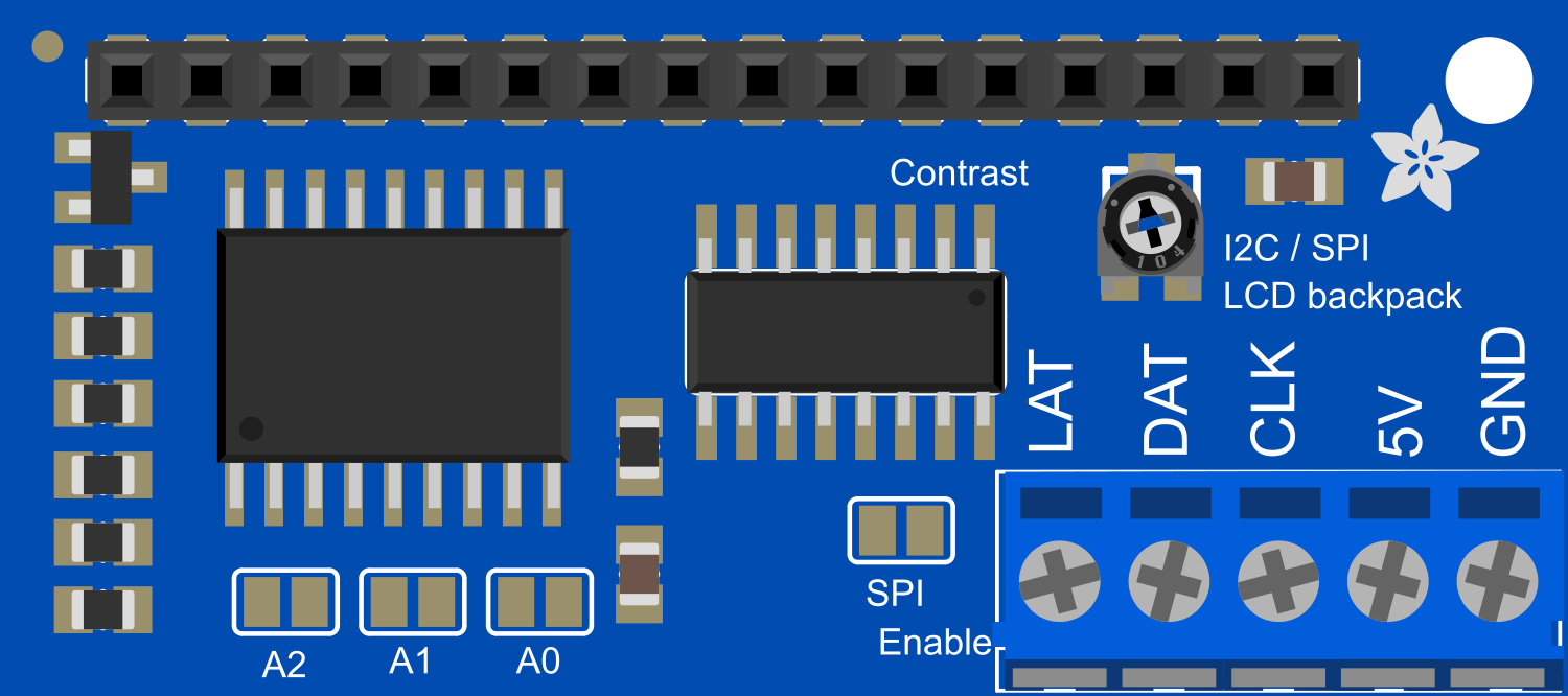
The Adafruit I2C+SPI LCD Backpack is a versatile breakout board designed to simplify the process of interfacing with I2C and SPI LCD displays. This component is ideal for hobbyists, engineers, and makers who require a visual output for their projects. It is commonly used in DIY electronics, interactive art installations, and in devices that need a user interface.

Explore Projects Built with Adafruit I2C+SPI LCD Backpack

Use Cirkit Designer to design, explore, and prototype these projects online. Some projects support real-time simulation. Click "Open Project" to start designing instantly!
Arduino Leonardo Controlled I2C LCD Display for Text Scrolling
Image of final year project: A project utilizing Adafruit I2C+SPI LCD Backpack in a practical application
This circuit features an Arduino Leonardo microcontroller connected to a 16x2 I2C LCD screen, powered by a 5V battery. The Arduino is programmed to display and continuously scroll a message on the LCD. The I2C communication protocol is used for the microcontroller to interface with the LCD, utilizing the SDA and SCL connections for data transfer.
Cirkit Designer LogoOpen Project in Cirkit Designer
ESP32 and I2C LCD Display for Data Visualization
Image of layar20x4I2C: A project utilizing Adafruit I2C+SPI LCD Backpack in a practical application
This circuit consists of an ESP32 Devkit V1 microcontroller connected to a 20x4 I2C LCD display. The ESP32 controls the LCD via I2C communication, with the SCL and SDA lines connected to GPIO pins D22 and D21, respectively, and provides power and ground connections to the display.
Cirkit Designer LogoOpen Project in Cirkit Designer
ESP32-Controlled I2C LCD Display
Image of ESP32I2CLCD: A project utilizing Adafruit I2C+SPI LCD Backpack in a practical application
This circuit connects an ESP32 microcontroller to an I2C LCD 16x2 display. The ESP32 powers the LCD and communicates with it via the I2C protocol using its SDA and SCL lines connected to the corresponding pins on the LCD. The embedded code on the ESP32 is programmed to display messages on the LCD screen in a loop, which can be used for user interface or status display purposes.
Cirkit Designer LogoOpen Project in Cirkit Designer
Wi-Fi Controlled RGB LED and OLED Display with ESP8266
Image of ESP thermometer reciever: A project utilizing Adafruit I2C+SPI LCD Backpack in a practical application
This circuit features an ESP8266 microcontroller interfaced with a 128x64 OLED display via I2C for visual output and an RGB LED controlled through current-limiting resistors. The ESP8266 provides power and control signals to both the display and the LED, enabling visual feedback and status indication.
Cirkit Designer LogoOpen Project in Cirkit Designer

Explore Projects Built with Adafruit I2C+SPI LCD Backpack

Use Cirkit Designer to design, explore, and prototype these projects online. Some projects support real-time simulation. Click "Open Project" to start designing instantly!
Image of final year project: A project utilizing Adafruit I2C+SPI LCD Backpack in a practical application
Arduino Leonardo Controlled I2C LCD Display for Text Scrolling
This circuit features an Arduino Leonardo microcontroller connected to a 16x2 I2C LCD screen, powered by a 5V battery. The Arduino is programmed to display and continuously scroll a message on the LCD. The I2C communication protocol is used for the microcontroller to interface with the LCD, utilizing the SDA and SCL connections for data transfer.
Cirkit Designer LogoOpen Project in Cirkit Designer
Image of layar20x4I2C: A project utilizing Adafruit I2C+SPI LCD Backpack in a practical application
ESP32 and I2C LCD Display for Data Visualization
This circuit consists of an ESP32 Devkit V1 microcontroller connected to a 20x4 I2C LCD display. The ESP32 controls the LCD via I2C communication, with the SCL and SDA lines connected to GPIO pins D22 and D21, respectively, and provides power and ground connections to the display.
Cirkit Designer LogoOpen Project in Cirkit Designer
Image of ESP32I2CLCD: A project utilizing Adafruit I2C+SPI LCD Backpack in a practical application
ESP32-Controlled I2C LCD Display
This circuit connects an ESP32 microcontroller to an I2C LCD 16x2 display. The ESP32 powers the LCD and communicates with it via the I2C protocol using its SDA and SCL lines connected to the corresponding pins on the LCD. The embedded code on the ESP32 is programmed to display messages on the LCD screen in a loop, which can be used for user interface or status display purposes.
Cirkit Designer LogoOpen Project in Cirkit Designer
Image of ESP thermometer reciever: A project utilizing Adafruit I2C+SPI LCD Backpack in a practical application
Wi-Fi Controlled RGB LED and OLED Display with ESP8266
This circuit features an ESP8266 microcontroller interfaced with a 128x64 OLED display via I2C for visual output and an RGB LED controlled through current-limiting resistors. The ESP8266 provides power and control signals to both the display and the LED, enabling visual feedback and status indication.
Cirkit Designer LogoOpen Project in Cirkit Designer

Common Applications and Use Cases

  • DIY electronics projects
  • User interfaces for devices
  • Interactive art installations
  • Prototyping and educational purposes
  • Displaying sensor readings or system statuses

Technical Specifications

Key Technical Details

  • Communication Protocols: I2C and SPI
  • Operating Voltage: 3.3V to 5V
  • Logic Level: 3.3V (5V tolerant)
  • Dimensions: 27mm x 18mm x 2mm

Pin Configuration and Descriptions

Pin Function Description
GND Ground Connect to system ground
VCC Power 3.3V to 5V input voltage
SDA I2C Data I2C data line
SCL I2C Clock I2C clock line
MOSI SPI Data In SPI Master Out Slave In
MISO SPI Data Out SPI Master In Slave Out (not used)
SCK SPI Clock SPI clock line
CS SPI Chip Select Active-low SPI chip select

Usage Instructions

How to Use the Component in a Circuit

  1. Power Connections:

    • Connect the VCC pin to a 3.3V or 5V power supply.
    • Connect the GND pin to the ground of your power supply.
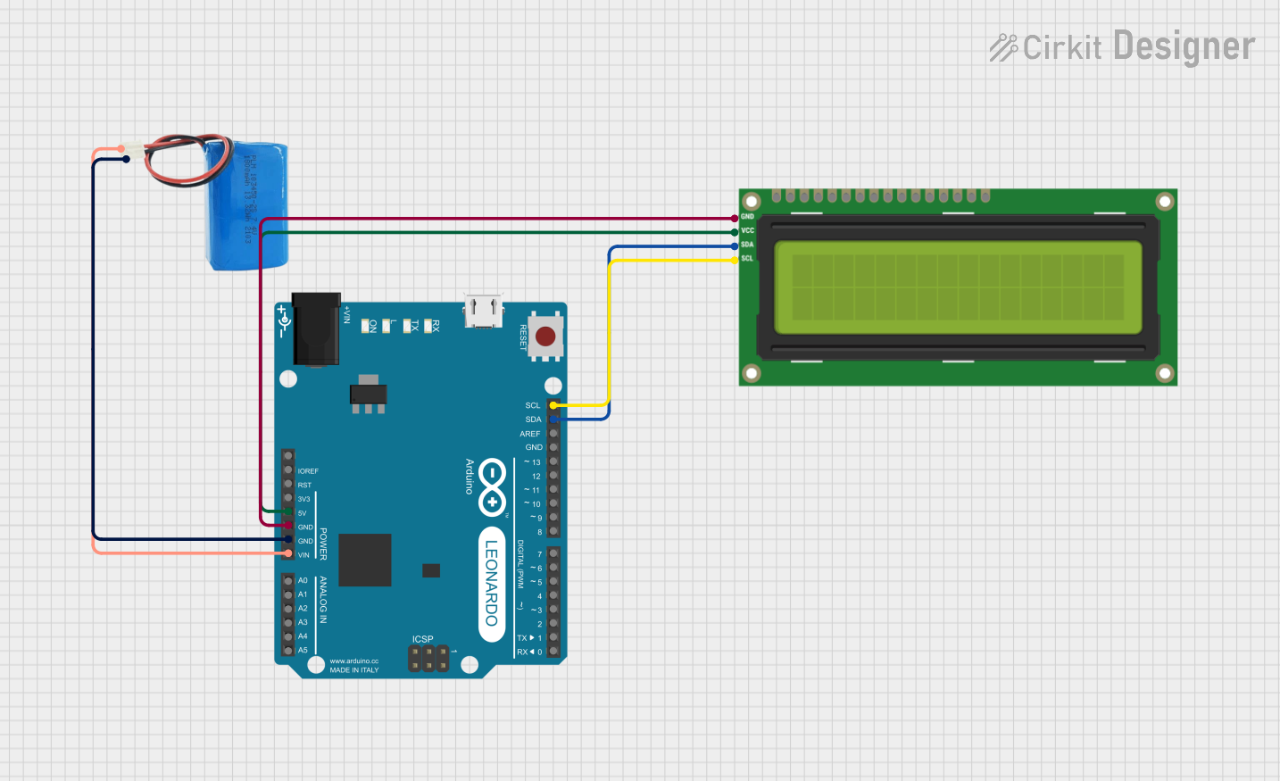
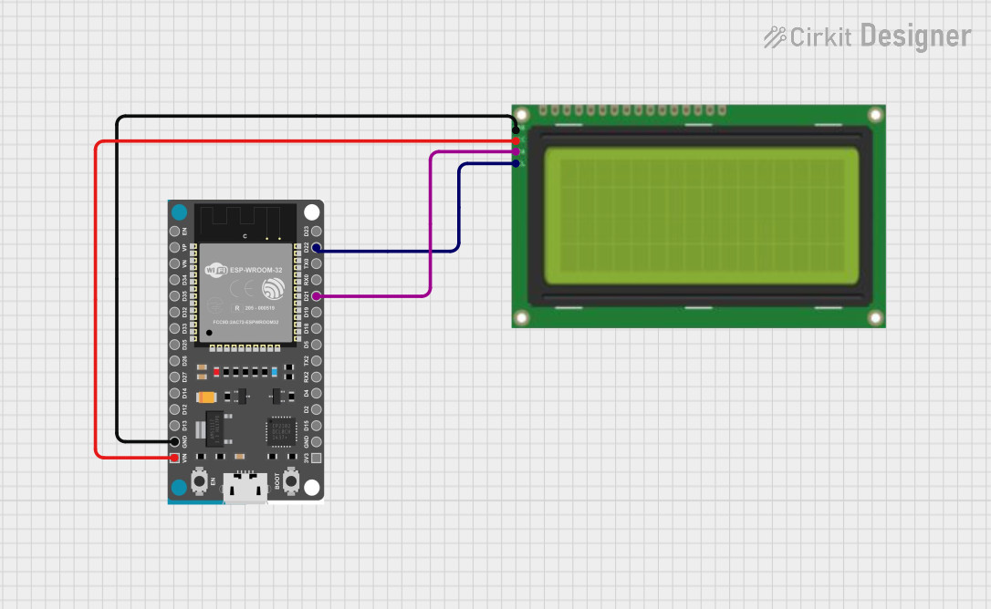
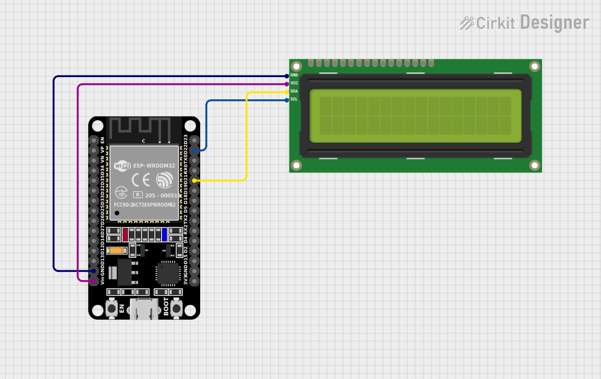
  2. I2C Communication:

    • Connect the SDA pin to the I2C data line on your microcontroller.
    • Connect the SCL pin to the I2C clock line on your microcontroller.
  3. SPI Communication:

    • Connect the MOSI pin to the SPI MOSI line on your microcontroller.
    • Connect the SCK pin to the SPI clock line on your microcontroller.
    • Connect the CS pin to a digital pin on your microcontroller for chip select.

Important Considerations and Best Practices

  • Ensure that the logic levels are compatible with your microcontroller.
  • Use pull-up resistors on the I2C lines if your microcontroller does not have them built-in.
  • For SPI communication, ensure that the CS pin is set to HIGH when the device is not in use.
  • Avoid long wires to minimize interference in the communication lines.

Example Code for Arduino UNO

#include <Wire.h> // Include the I2C library (required)

// Initialize the I2C address for the LCD Backpack
const int lcdAddress = 0x27;

void setup() {
  Wire.begin(); // Start the I2C interface
  // Initialize the LCD with the number of columns and rows
  // For example, for a 16x2 LCD:
  // lcd.begin(16, 2);
}

void loop() {
  // Your code to interact with the LCD goes here
  // Example: Write "Hello, World!" to the LCD
  // lcd.print("Hello, World!");
  // Add a delay if necessary
  // delay(1000);
}

Note: This is a basic example to demonstrate I2C communication setup. You will need to include a library that supports the specific LCD you are using, such as the LiquidCrystal_I2C library, and initialize the LCD object accordingly.

Troubleshooting and FAQs

Common Issues Users Might Face

  • Display Not Powering On: Check the power connections and ensure that the voltage is within the specified range.
  • No Text on Display: Verify that the I2C or SPI connections are correct and that the correct communication protocol is selected.
  • Garbled Text: Ensure that the LCD is properly initialized in your code and that the correct address is used.

Solutions and Tips for Troubleshooting

  • Double-check wiring connections to ensure they are secure and correct.
  • Use a multimeter to verify that power is reaching the component.
  • Check for any soldering issues on the backpack pins.
  • Ensure that the microcontroller's libraries and code are up to date and correctly configured for the display.

FAQs

Q: Can I use this backpack with any LCD? A: The backpack is designed to work with most character LCDs that have a compatible pinout. Check the datasheet of your LCD to ensure compatibility.

Q: How do I change between I2C and SPI modes? A: The mode is determined by how you wire the backpack to your microcontroller and how you initialize it in your code. Use the appropriate library and initialization for the chosen protocol.

Q: What is the maximum length for the I2C or SPI cables? A: The maximum cable length can vary, but it is generally recommended to keep the cables as short as possible (a few centimeters to a meter) to ensure reliable communication. Longer cables may require lower communication speeds or the use of signal repeaters/extenders.

Q: Can I power the backpack with 5V if my microcontroller operates at 3.3V? A: Yes, the backpack is 5V tolerant, but ensure that the logic level for communication matches your microcontroller's operating voltage. Use logic level converters if necessary.