How to Use h-bridge motor driver: Examples, Pinouts, and Specs
Introduction
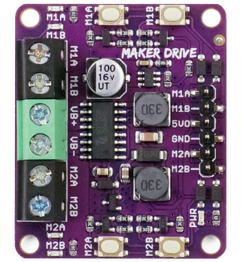
The H-Bridge Motor Driver (Manufacturer: Maker Drive, Part ID: MOTOR DRIVER) is an electronic circuit designed to control the direction and speed of DC motors. By enabling voltage to be applied across a motor in either direction, it allows for forward, reverse, and braking operations. This makes it an essential component in robotics, automation, and other motor control applications.
Explore Projects Built with h-bridge motor driver
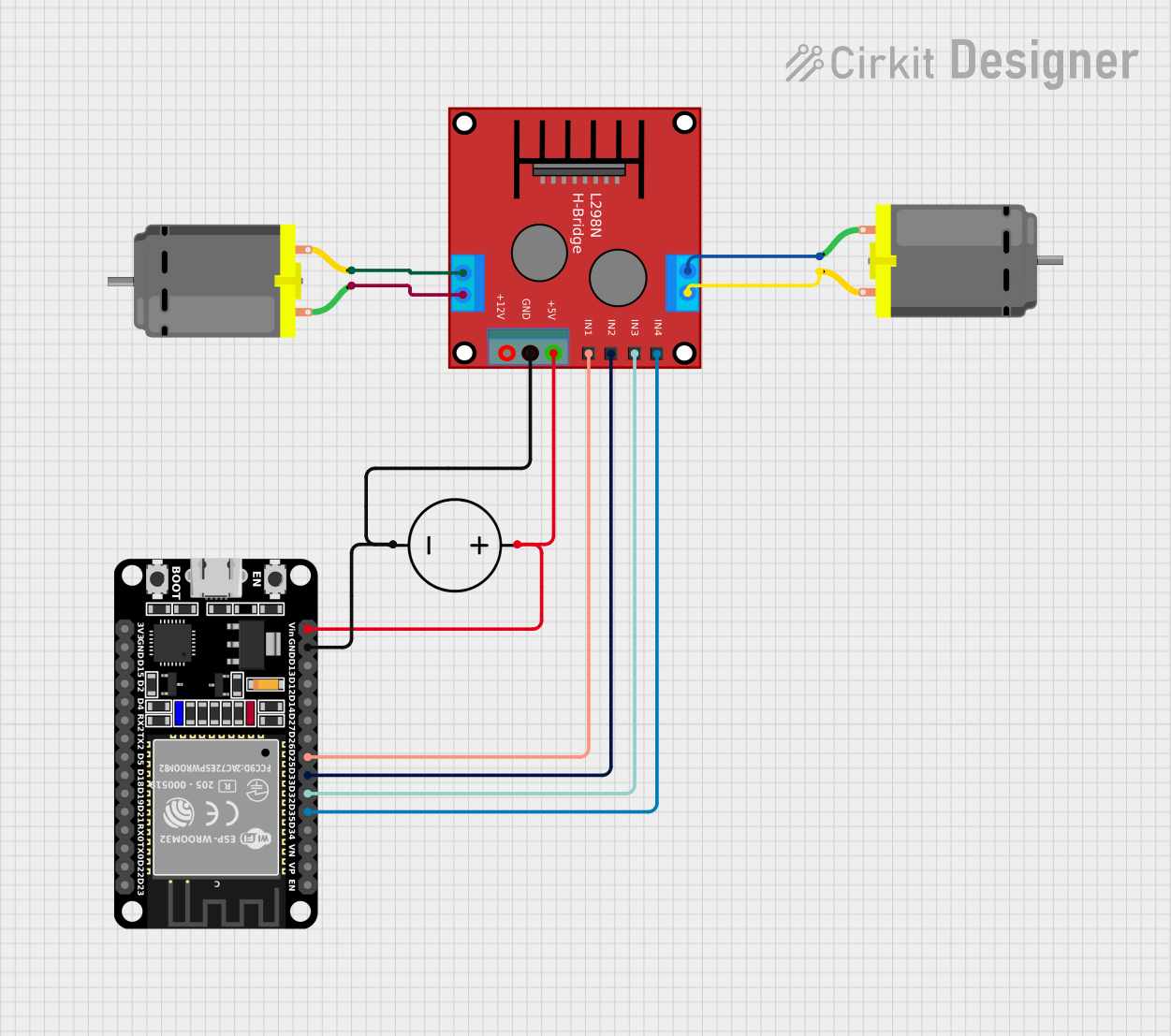
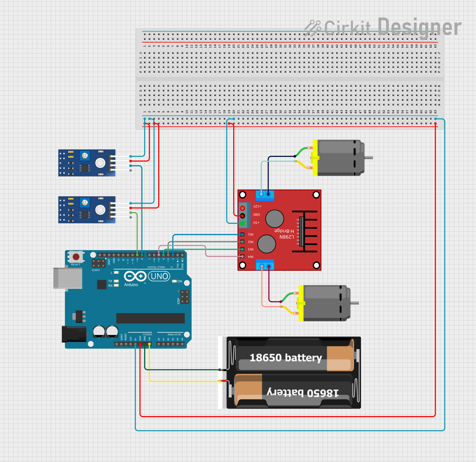

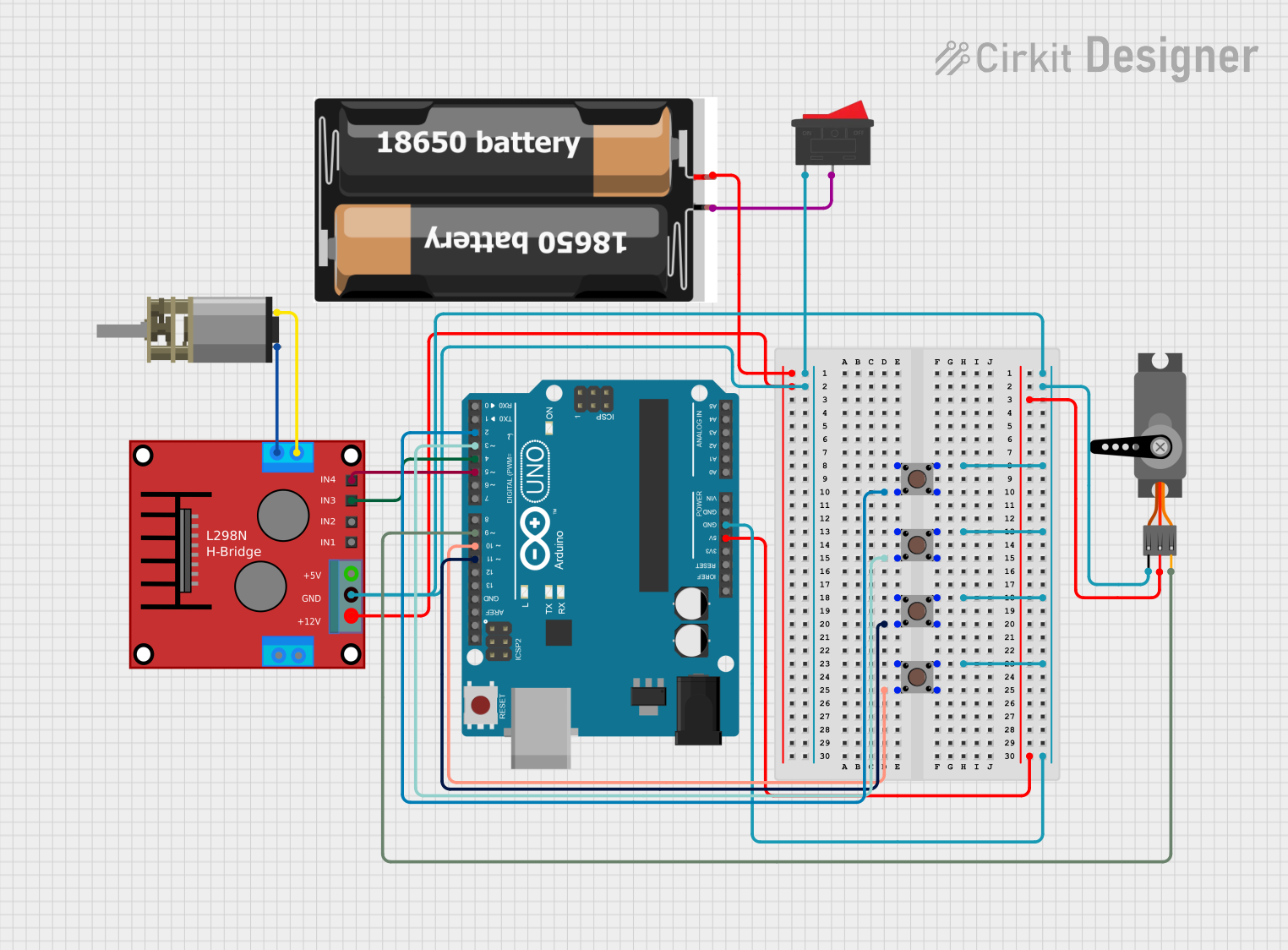
Explore Projects Built with h-bridge motor driver
Common Applications and Use Cases
- Robotics: Controlling the movement of robot wheels or arms.
- Automation: Driving conveyor belts or actuators.
- Remote-controlled vehicles: Enabling forward and reverse motion.
- DIY projects: Motorized systems such as fans, doors, or small vehicles.
Technical Specifications
The following table outlines the key technical details of the Maker Drive H-Bridge Motor Driver:
| Parameter | Value |
|---|---|
| Operating Voltage | 5V to 12V |
| Maximum Output Current | 1.5A per channel (continuous) |
| Peak Current | 2A per channel (short duration) |
| Logic Voltage | 3.3V or 5V (compatible with MCUs) |
| Number of Channels | 2 (dual motor control) |
| Control Inputs | IN1, IN2, ENA (per channel) |
| Output Terminals | OUT1, OUT2 (per channel) |
| Protection Features | Overcurrent and thermal shutdown |
Pin Configuration and Descriptions
The H-Bridge Motor Driver has the following pin configuration:
Input Pins
| Pin Name | Description |
|---|---|
| IN1 | Input signal to control motor direction (Channel 1). |
| IN2 | Input signal to control motor direction (Channel 1). |
| ENA | Enable pin for Channel 1 (PWM for speed control). |
| IN3 | Input signal to control motor direction (Channel 2). |
| IN4 | Input signal to control motor direction (Channel 2). |
| ENB | Enable pin for Channel 2 (PWM for speed control). |
Output Pins
| Pin Name | Description |
|---|---|
| OUT1 | Motor output terminal 1 (Channel 1). |
| OUT2 | Motor output terminal 2 (Channel 1). |
| OUT3 | Motor output terminal 1 (Channel 2). |
| OUT4 | Motor output terminal 2 (Channel 2). |
Power Pins
| Pin Name | Description |
|---|---|
| VCC | Power supply input (5V to 12V). |
| GND | Ground connection. |
Usage Instructions
How to Use the Component in a Circuit
- Connect Power Supply:
- Connect the VCC pin to a power source (5V to 12V) and GND to ground.
- Connect the Motor:
- Attach the motor terminals to the output pins (OUT1 and OUT2 for Channel 1, OUT3 and OUT4 for Channel 2).
- Control Inputs:
- Use IN1 and IN2 to control the direction of the motor for Channel 1. Similarly, use IN3 and IN4 for Channel 2.
- Apply a PWM signal to ENA (Channel 1) or ENB (Channel 2) to control motor speed.
- Microcontroller Interface:
- Connect the control pins (IN1, IN2, ENA, etc.) to the GPIO pins of a microcontroller (e.g., Arduino UNO).
Important Considerations and Best Practices
- Ensure the power supply voltage matches the motor's operating voltage.
- Use appropriate heat sinks or cooling if operating near the maximum current rating.
- Avoid short circuits between output terminals to prevent damage.
- Use pull-down resistors on control pins to avoid floating states when the microcontroller is powered off.
Example Code for Arduino UNO
Below is an example code to control a DC motor using the H-Bridge Motor Driver:
// Define control pins for Channel 1
const int IN1 = 9;  // Direction control pin 1
const int IN2 = 8;  // Direction control pin 2
const int ENA = 10; // Speed control (PWM) pin

void setup() {
  // Set control pins as outputs
  pinMode(IN1, OUTPUT);
  pinMode(IN2, OUTPUT);
  pinMode(ENA, OUTPUT);
}

void loop() {
  // Rotate motor forward
  digitalWrite(IN1, HIGH); // Set IN1 high
  digitalWrite(IN2, LOW);  // Set IN2 low
  analogWrite(ENA, 128);   // Set speed to 50% (PWM value: 128)
  delay(2000);             // Run for 2 seconds

  // Rotate motor backward
  digitalWrite(IN1, LOW);  // Set IN1 low
  digitalWrite(IN2, HIGH); // Set IN2 high
  analogWrite(ENA, 128);   // Set speed to 50% (PWM value: 128)
  delay(2000);             // Run for 2 seconds

  // Stop motor
  digitalWrite(IN1, LOW);  // Set IN1 low
  digitalWrite(IN2, LOW);  // Set IN2 low
  analogWrite(ENA, 0);     // Set speed to 0
  delay(2000);             // Wait for 2 seconds
}
Troubleshooting and FAQs
Common Issues and Solutions
Motor Does Not Turn On:
- Check the power supply voltage and connections.
- Ensure the ENA/ENB pins are receiving a valid PWM signal.
- Verify that the motor is properly connected to the output terminals.
Motor Spins in the Wrong Direction:
- Swap the IN1 and IN2 signals (or IN3 and IN4 for Channel 2).
- Verify the logic levels sent to the control pins.
Overheating of the Driver:
- Ensure the current drawn by the motor does not exceed the driver's maximum rating.
- Use a heat sink or cooling fan if necessary.
No Response from the Motor Driver:
- Check for loose connections or damaged wires.
- Verify that the microcontroller is correctly programmed and powered.
FAQs
Q: Can I use this driver with a 3.3V microcontroller?
A: Yes, the driver is compatible with both 3.3V and 5V logic levels.
Q: Can I control two motors simultaneously?
A: Yes, the driver supports dual-channel operation, allowing independent control of two motors.
Q: What happens if I connect the motor terminals incorrectly?
A: The motor may not function as expected. Ensure proper wiring to avoid damage to the driver or motor.
Q: Can I use this driver for stepper motors?
A: No, this driver is designed for DC motors. Use a dedicated stepper motor driver for stepper motors.