
Cirkit Designer
Your all-in-one circuit design IDE
Home /
Component Documentation
How to Use Adafruit Feather M0 RFM9x LoRa: Examples, Pinouts, and Specs
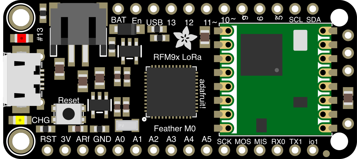
 Design with Adafruit Feather M0 RFM9x LoRa in Cirkit Designer
Introduction
The Adafruit Feather M0 RFM9x LoRa is a compact and versatile microcontroller board designed for IoT (Internet of Things) applications. It features an ARM Cortex-M0 processor and an integrated RFM9x LoRa radio module, enabling long-range wireless communication. This board is part of Adafruit's Feather ecosystem, making it compatible with a wide range of FeatherWing add-on boards for extended functionality.
Explore Projects Built with Adafruit Feather M0 RFM9x LoRa
Arduino MKR WiFi 1010 and Adafruit RFM9x LoRa Radio Communication System

This circuit connects an Adafruit RFM9x LoRa Radio module to an Arduino MKR WiFi 1010 for wireless communication capabilities. The LoRa module's SPI interface (MOSI, MISO, SCK, CS) is connected to the corresponding SPI pins on the Arduino, allowing for serial data transfer between the devices. Additionally, the LoRa module's reset (RST) and interrupt (DIO0) pins are connected to digital pins on the Arduino for control and asynchronous communication.
Open Project in Cirkit DesignerESP32-Controlled LoRa Communication Module
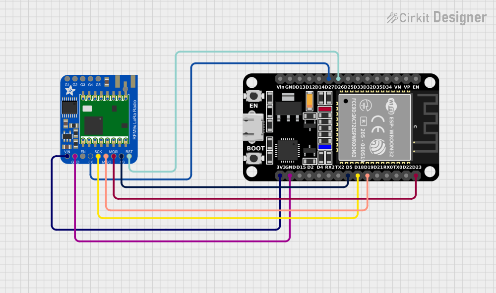
This circuit connects an ESP32 microcontroller to an Adafruit RFM9x LoRa Radio module for wireless communication. The ESP32's GPIO pins are wired to the LoRa module's SPI interface (MOSI, MISO, SCK, CS), interrupt (DIO0), and reset (RST) to enable data transmission and reception over LoRa. The ESP32 also provides power (3V3) and ground (GND) to the LoRa module.
Open Project in Cirkit DesignerXiao ESP32 C3 and Adafruit RFM9x LoRa Radio Communication Module
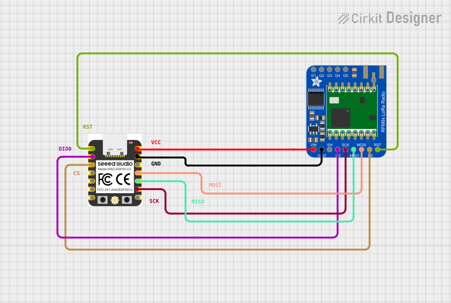
This circuit connects a Xiao ESP32 C3 microcontroller to an Adafruit RFM9x LoRa Radio module. The ESP32 C3 provides power to the LoRa module and interfaces with it using SPI communication (SCK, MISO, MOSI, CS) and control lines (RST, DIO0). This setup is likely intended for wireless communication using LoRa technology, with the ESP32 handling data processing and network protocol tasks.
Open Project in Cirkit DesignerESP32 and RFM95 LoRa Transmitter with Inductor-Based Antenna
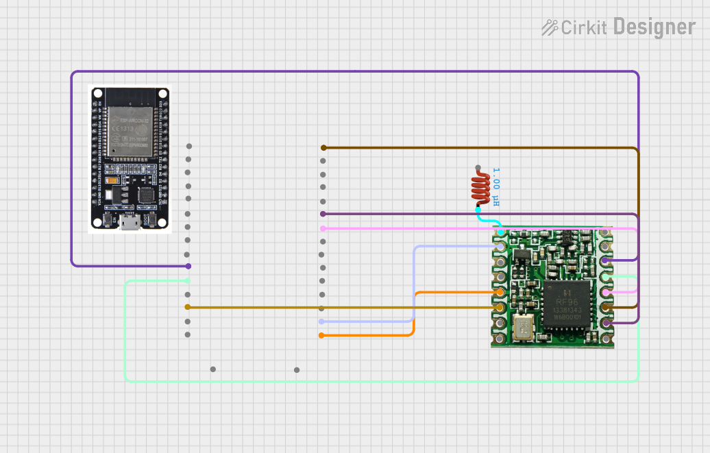
This circuit is a LoRa transmitter system that uses an ESP32 microcontroller to communicate with an RFM95 LoRa module. The ESP32 initializes the LoRa module and sends periodic messages wirelessly, with an inductor connected to the antenna pin of the RFM95 for signal tuning.
Open Project in Cirkit DesignerExplore Projects Built with Adafruit Feather M0 RFM9x LoRa
Arduino MKR WiFi 1010 and Adafruit RFM9x LoRa Radio Communication System
This circuit connects an Adafruit RFM9x LoRa Radio module to an Arduino MKR WiFi 1010 for wireless communication capabilities. The LoRa module's SPI interface (MOSI, MISO, SCK, CS) is connected to the corresponding SPI pins on the Arduino, allowing for serial data transfer between the devices. Additionally, the LoRa module's reset (RST) and interrupt (DIO0) pins are connected to digital pins on the Arduino for control and asynchronous communication.
Open Project in Cirkit DesignerESP32-Controlled LoRa Communication Module
This circuit connects an ESP32 microcontroller to an Adafruit RFM9x LoRa Radio module for wireless communication. The ESP32's GPIO pins are wired to the LoRa module's SPI interface (MOSI, MISO, SCK, CS), interrupt (DIO0), and reset (RST) to enable data transmission and reception over LoRa. The ESP32 also provides power (3V3) and ground (GND) to the LoRa module.
Open Project in Cirkit DesignerXiao ESP32 C3 and Adafruit RFM9x LoRa Radio Communication Module
This circuit connects a Xiao ESP32 C3 microcontroller to an Adafruit RFM9x LoRa Radio module. The ESP32 C3 provides power to the LoRa module and interfaces with it using SPI communication (SCK, MISO, MOSI, CS) and control lines (RST, DIO0). This setup is likely intended for wireless communication using LoRa technology, with the ESP32 handling data processing and network protocol tasks.
Open Project in Cirkit DesignerESP32 and RFM95 LoRa Transmitter with Inductor-Based Antenna
This circuit is a LoRa transmitter system that uses an ESP32 microcontroller to communicate with an RFM95 LoRa module. The ESP32 initializes the LoRa module and sends periodic messages wirelessly, with an inductor connected to the antenna pin of the RFM95 for signal tuning.
Open Project in Cirkit DesignerCommon Applications and Use Cases
- Long-range wireless sensor networks
- IoT devices and smart home systems
- Environmental monitoring and data logging
- Remote control and telemetry systems
- Agricultural and industrial automation
Technical Specifications
Key Technical Details
| Specification | Value |
|---|---|
| Microcontroller | ATSAMD21G18 ARM Cortex-M0 |
| Operating Voltage | 3.3V |
| Clock Speed | 48 MHz |
| Flash Memory | 256 KB |
| SRAM | 32 KB |
| LoRa Radio Module | RFM95/96/97/98 (Semtech SX1276 chipset) |
| Frequency Range | 868 MHz (EU) / 915 MHz (US) |
| Communication Interfaces | UART, SPI, I2C |
| GPIO Pins | 20 (8 PWM-capable) |
| Analog Inputs | 6 (12-bit ADC) |
| Power Supply | USB or LiPo battery (3.7V) |
| Dimensions | 51mm x 23mm x 8mm |
Pin Configuration and Descriptions
| Pin Name | Description |
|---|---|
| VIN | Input voltage (3.7V LiPo battery or USB power) |
| 3V | Regulated 3.3V output |
| GND | Ground connection |
| A0–A5 | Analog input pins (12-bit ADC) |
| D0–D13 | Digital I/O pins (some support PWM) |
| SDA | I2C data line |
| SCL | I2C clock line |
| MOSI | SPI Master Out Slave In |
| MISO | SPI Master In Slave Out |
| SCK | SPI clock |
| RFM9x CS | Chip select for the LoRa module |
| RFM9x IRQ | Interrupt request pin for the LoRa module |
| RFM9x RST | Reset pin for the LoRa module |
| EN | Enable pin to turn the board on/off |
| BAT | LiPo battery voltage monitoring pin |
Usage Instructions
How to Use the Component in a Circuit
Powering the Board:
- Connect a 3.7V LiPo battery to the JST connector or power the board via the micro-USB port.
- Ensure the power source provides sufficient current for both the microcontroller and the LoRa module.
Connecting Peripherals:
- Use the GPIO pins for digital input/output or PWM signals.
- Connect sensors or modules via I2C (SDA/SCL) or SPI (MOSI/MISO/SCK) interfaces.
Programming the Board:
- Install the Arduino IDE and add the Adafruit SAMD Boards package via the Board Manager.
- Select "Adafruit Feather M0" as the board type in the Arduino IDE.
- Connect the board to your computer via USB and upload your code.
Using the LoRa Module:
- Install the Adafruit RadioHead library in the Arduino IDE.
- Configure the LoRa module's frequency and settings in your code.
Important Considerations and Best Practices
- Voltage Levels: The board operates at 3.3V logic. Avoid connecting 5V signals directly to the GPIO pins.
- Antenna Connection: Attach a suitable antenna to the LoRa module for optimal range and performance.
- Battery Monitoring: Use the BAT pin to monitor the LiPo battery voltage in your code.
- Heat Management: Avoid placing the board in enclosed spaces without ventilation during high-power operation.
Example Code for LoRa Communication with Arduino UNO
#include <SPI.h>
#include <RH_RF95.h>

// Define LoRa module pins
#define RFM95_CS 8    // Chip select pin
#define RFM95_RST 4   // Reset pin
#define RFM95_INT 3   // Interrupt pin

// Frequency for LoRa communication (adjust based on region)
#define RF95_FREQ 915.0  // 915 MHz for US, 868 MHz for EU

// Create an instance of the RF95 driver
RH_RF95 rf95(RFM95_CS, RFM95_INT);

void setup() {
  Serial.begin(9600);
  while (!Serial);

  // Initialize LoRa module
  pinMode(RFM95_RST, OUTPUT);
  digitalWrite(RFM95_RST, HIGH);
  delay(10);
  digitalWrite(RFM95_RST, LOW);
  delay(10);
  digitalWrite(RFM95_RST, HIGH);
  delay(10);

  if (!rf95.init()) {
    Serial.println("LoRa module initialization failed!");
    while (1);
  }
  Serial.println("LoRa module initialized.");

  // Set frequency
  if (!rf95.setFrequency(RF95_FREQ)) {
    Serial.println("Failed to set frequency!");
    while (1);
  }
  Serial.print("Frequency set to: ");
  Serial.println(RF95_FREQ);

  // Set transmission power
  rf95.setTxPower(13, false);  // 13 dBm, PA_BOOST disabled
}

void loop() {
  // Send a test message
  Serial.println("Sending message...");
  const char *message = "Hello, LoRa!";
  rf95.send((uint8_t *)message, strlen(message));
  rf95.waitPacketSent();
  Serial.println("Message sent!");

  // Wait for a response
  if (rf95.waitAvailableTimeout(3000)) {
    uint8_t buf[RH_RF95_MAX_MESSAGE_LEN];
    uint8_t len = sizeof(buf);
    if (rf95.recv(buf, &len)) {
      Serial.print("Received: ");
      Serial.println((char *)buf);
    } else {
      Serial.println("Receive failed.");
    }
  } else {
    Serial.println("No response received.");
  }

  delay(5000);  // Wait before sending the next message
}
Troubleshooting and FAQs
Common Issues Users Might Face
LoRa Module Not Initializing:
- Ensure the RFM9x CS, RST, and IRQ pins are correctly connected and defined in your code.
- Verify that the LoRa module's frequency matches your region's regulations.
No Communication Between Devices:
- Check that both devices are using the same frequency and settings (e.g., spreading factor, bandwidth).
- Ensure the antennas are properly connected and positioned.
Board Not Recognized by Arduino IDE:
- Install the correct USB drivers for the Adafruit Feather M0.
- Verify that the correct board type and COM port are selected in the Arduino IDE.
Solutions and Tips for Troubleshooting
- Use a multimeter to check power supply voltages and continuity of connections.
- Test the board with a simple "blink" sketch to confirm basic functionality.
- Refer to the Adafruit Feather M0 RFM9x LoRa product page and forums for additional support and resources.