How to Use Lora Ra-02: Examples, Pinouts, and Specs
Introduction
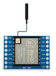
The Lora Ra-02 is a low-power, long-range wireless transceiver module designed for IoT applications. It operates on the LoRa (Long Range) protocol, which enables communication over distances of several kilometers while consuming minimal power. This makes it an excellent choice for battery-operated devices and applications requiring reliable, long-range communication.
Explore Projects Built with Lora Ra-02

Explore Projects Built with Lora Ra-02
Common Applications and Use Cases
- Smart agriculture (e.g., soil moisture monitoring, weather stations)
- Industrial IoT (e.g., asset tracking, predictive maintenance)
- Smart cities (e.g., parking sensors, environmental monitoring)
- Home automation and security systems
- Remote data logging and telemetry
Technical Specifications
The Lora Ra-02 module is based on the Semtech SX1278 chip and supports the LoRa modulation technique for robust and efficient communication.
Key Technical Details
| Parameter | Specification |
|---|---|
| Operating Voltage | 1.8V to 3.7V |
| Operating Current | 10.8mA (transmit), 10.3mA (receive) |
| Sleep Current | < 200nA |
| Frequency Range | 433 MHz |
| Modulation Technique | LoRa (Long Range) |
| Maximum Data Rate | 300 kbps |
| Communication Range | Up to 10 km (line of sight) |
| Output Power | +20 dBm (100 mW) |
| Sensitivity | -148 dBm |
| Operating Temperature | -40°C to +85°C |
| Dimensions | 17 x 16 mm |
Pin Configuration and Descriptions
The Lora Ra-02 module has 16 pins. Below is the pinout and description:
| Pin Number | Pin Name | Description |
|---|---|---|
| 1 | GND | Ground |
| 2 | DIO5 | Digital I/O pin 5 (used for interrupts or status indication) |
| 3 | DIO4 | Digital I/O pin 4 (used for interrupts or status indication) |
| 4 | DIO3 | Digital I/O pin 3 (used for interrupts or status indication) |
| 5 | DIO2 | Digital I/O pin 2 (used for interrupts or status indication) |
| 6 | DIO1 | Digital I/O pin 1 (used for interrupts or status indication) |
| 7 | DIO0 | Digital I/O pin 0 (used for interrupts or status indication) |
| 8 | NSS | Chip Select (active low) |
| 9 | MISO | SPI Master-In-Slave-Out (data output from the module) |
| 10 | MOSI | SPI Master-Out-Slave-In (data input to the module) |
| 11 | SCK | SPI Clock |
| 12 | RESET | Reset pin (active low) |
| 13 | 3.3V | Power supply input (3.3V recommended) |
| 14 | ANT | Antenna connection |
| 15 | GND | Ground |
| 16 | GND | Ground |
Usage Instructions
How to Use the Lora Ra-02 in a Circuit
- Power Supply: Connect the
3.3Vpin to a stable 3.3V power source. Ensure the ground (GND) pins are connected to the circuit's ground. - SPI Communication: Connect the
MOSI,MISO,SCK, andNSSpins to the corresponding SPI pins of your microcontroller. - Antenna: Attach a suitable 433 MHz antenna to the
ANTpin for optimal performance. - Reset: Use the
RESETpin to initialize the module during startup or when needed. - Interrupts: Use the
DIOpins for interrupt-driven communication if required by your application.
Important Considerations and Best Practices
- Voltage Levels: The module operates at 3.3V. If using a 5V microcontroller (e.g., Arduino UNO), use a level shifter for the SPI pins to avoid damaging the module.
- Antenna Placement: Ensure the antenna is placed away from other components to minimize interference and maximize range.
- Power Supply: Use a low-noise power supply to avoid communication issues.
- Heat Management: Operate the module within the specified temperature range to prevent overheating.
Example Code for Arduino UNO
Below is an example of how to use the Lora Ra-02 module with an Arduino UNO. This code uses the popular LoRa library.
#include <SPI.h>
#include <LoRa.h>

// Define the pins for SPI communication
#define NSS 10  // Chip Select pin
#define RESET 9 // Reset pin
#define DIO0 2  // Interrupt pin

void setup() {
  Serial.begin(9600); // Initialize serial communication
  while (!Serial);

  Serial.println("Initializing LoRa module...");

  // Initialize LoRa module
  LoRa.setPins(NSS, RESET, DIO0); // Set SPI pins
  if (!LoRa.begin(433E6)) {       // Initialize at 433 MHz
    Serial.println("LoRa initialization failed!");
    while (1);
  }

  Serial.println("LoRa initialized successfully!");
}

void loop() {
  Serial.println("Sending packet...");
  LoRa.beginPacket();             // Start a new packet
  LoRa.print("Hello, LoRa!");     // Add data to the packet
  LoRa.endPacket();               // Send the packet

  delay(5000); // Wait 5 seconds before sending the next packet
}
Notes:
- Install the
LoRalibrary in the Arduino IDE before uploading the code. - Modify the frequency (
433E6) if using a different frequency band.
Troubleshooting and FAQs
Common Issues and Solutions
Module Not Responding
- Cause: Incorrect wiring or power supply issues.
- Solution: Double-check all connections and ensure the module is powered with 3.3V.
Poor Communication Range
- Cause: Improper antenna placement or interference.
- Solution: Use a high-quality antenna and place it away from other components.
Data Transmission Fails
- Cause: Incorrect SPI configuration or mismatched frequency.
- Solution: Verify SPI connections and ensure both transmitter and receiver are set to the same frequency.
Overheating
- Cause: Operating outside the specified temperature range.
- Solution: Ensure the module is used within -40°C to +85°C.
FAQs
Q: Can I use the Lora Ra-02 with a 5V microcontroller?
A: Yes, but you must use a level shifter for the SPI pins to step down the voltage to 3.3V.
Q: What is the maximum range of the Lora Ra-02?
A: The module can achieve up to 10 km range in line-of-sight conditions. However, obstacles and interference may reduce the range.
Q: Can I use multiple Lora Ra-02 modules in the same network?
A: Yes, you can use multiple modules, but ensure they operate on the same frequency and use unique addresses for communication.
Q: Does the module support encryption?
A: Yes, the LoRa protocol supports AES-128 encryption for secure communication.