How to Use Step Down Converter (EN): Examples, Pinouts, and Specs
Introduction
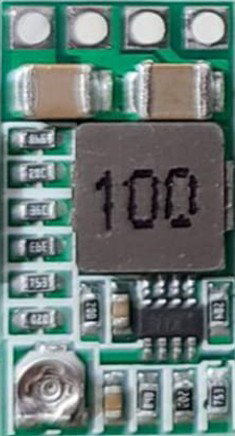
A Step Down Converter, also known as a buck converter, is a DC-DC power converter that reduces a higher input voltage to a lower output voltage while maintaining high efficiency. It achieves this by using a combination of an inductor, a switch (typically a transistor), and a diode to regulate the voltage. Step down converters are widely used in power supply systems due to their compact size, efficiency, and ability to handle varying loads.
Explore Projects Built with Step Down Converter (EN)


Explore Projects Built with Step Down Converter (EN)
Common Applications and Use Cases
- Powering low-voltage devices (e.g., microcontrollers, sensors) from higher voltage sources.
- Battery-powered systems to regulate voltage levels.
- Voltage regulation in automotive electronics.
- Renewable energy systems, such as solar panels, to step down voltage for storage or usage.
- Consumer electronics, such as smartphones and laptops, for efficient power management.
Technical Specifications
Below are the general technical specifications for a typical Step Down Converter (EN). Specific values may vary depending on the model or manufacturer.
Key Technical Details
- Input Voltage Range: 4.5V to 40V
- Output Voltage Range: 1.25V to 37V (adjustable)
- Output Current: Up to 3A (varies by model)
- Efficiency: Up to 92% (depending on load and input/output voltage)
- Switching Frequency: 150 kHz (typical)
- Operating Temperature: -40°C to +85°C
- Protection Features: Overcurrent protection, thermal shutdown, and short-circuit protection.
Pin Configuration and Descriptions
The Step Down Converter typically has the following pins:
| Pin Name | Description |
|---|---|
| VIN | Input voltage pin. Connect the higher input voltage source to this pin. |
| GND | Ground pin. Connect to the ground of the circuit. |
| VOUT | Output voltage pin. Provides the stepped-down voltage to the load. |
| EN | Enable pin. Used to turn the converter on or off. High = Enabled, Low = Disabled. |
| FB | Feedback pin. Used to set the output voltage by connecting a resistor divider. |
Usage Instructions
How to Use the Component in a Circuit
Connect the Input Voltage:
- Connect the positive terminal of the input voltage source to the
VINpin. - Connect the negative terminal of the input voltage source to the
GNDpin.
- Connect the positive terminal of the input voltage source to the
Set the Output Voltage:
- Use a resistor divider network connected to the
FBpin to set the desired output voltage. - The output voltage can be calculated using the formula: [ V_{OUT} = V_{REF} \times \left(1 + \frac{R1}{R2}\right) ] where ( V_{REF} ) is typically 1.25V, and ( R1 ) and ( R2 ) are the resistors in the divider.
- Use a resistor divider network connected to the
Connect the Load:
- Connect the load to the
VOUTpin andGND.
- Connect the load to the
Enable the Converter:
- To enable the converter, apply a high signal (e.g., 5V) to the
ENpin. To disable it, apply a low signal (e.g., 0V).
- To enable the converter, apply a high signal (e.g., 5V) to the
Add External Components:
- Place an input capacitor (e.g., 10µF) between
VINandGNDto stabilize the input voltage. - Place an output capacitor (e.g., 22µF) between
VOUTandGNDto reduce output voltage ripple. - Use an appropriate inductor value based on the input/output voltage and current requirements.
- Place an input capacitor (e.g., 10µF) between
Important Considerations and Best Practices
- Ensure the input voltage is within the specified range to avoid damaging the converter.
- Select an inductor with a current rating higher than the maximum load current.
- Use low Equivalent Series Resistance (ESR) capacitors for better performance.
- Avoid exceeding the maximum output current rating to prevent overheating or damage.
- Place the converter and associated components close together on the PCB to minimize noise and losses.
Example: Using with an Arduino UNO
The Step Down Converter can be used to power an Arduino UNO from a higher voltage source (e.g., a 12V battery). Below is an example circuit and code:
Circuit Connections
- Connect the 12V battery positive terminal to
VINand negative terminal toGND. - Set the output voltage to 5V using the feedback resistor divider.
- Connect the
VOUTpin to the Arduino UNO's 5V pin andGNDto the Arduino's GND.
Example Code
// Example code to blink an LED using Arduino UNO powered by a Step Down Converter

const int ledPin = 13; // Pin connected to the onboard LED

void setup() {
  pinMode(ledPin, OUTPUT); // Set the LED pin as an output
}

void loop() {
  digitalWrite(ledPin, HIGH); // Turn the LED on
  delay(1000);               // Wait for 1 second
  digitalWrite(ledPin, LOW);  // Turn the LED off
  delay(1000);               // Wait for 1 second
}
Troubleshooting and FAQs
Common Issues and Solutions
No Output Voltage:
- Check if the
ENpin is connected to a high signal (enabled). - Verify the input voltage is within the specified range.
- Inspect the connections for loose wires or incorrect polarity.
- Check if the
Output Voltage is Incorrect:
- Recalculate the resistor divider values for the
FBpin. - Ensure the feedback resistors are properly connected and not damaged.
- Recalculate the resistor divider values for the
Excessive Heat:
- Ensure the load current does not exceed the converter's maximum rating.
- Use a heatsink or improve ventilation if necessary.
High Output Ripple:
- Add or increase the value of the output capacitor.
- Use low ESR capacitors for better filtering.
FAQs
Q1: Can I use the Step Down Converter with an AC input?
A1: No, the Step Down Converter is designed for DC input only. Use a rectifier and filter circuit to convert AC to DC before using the converter.
Q2: What happens if I exceed the input voltage range?
A2: Exceeding the input voltage range can damage the converter. Always ensure the input voltage is within the specified range.
Q3: How do I calculate the inductor value?
A3: The inductor value depends on the input/output voltage, switching frequency, and load current. Refer to the manufacturer's datasheet for detailed calculations.
Q4: Can I use the Step Down Converter to charge a battery?
A4: Yes, but ensure the output voltage and current are suitable for the battery type. Use additional circuitry for proper charging control.