
How to Use MCP9808 I2C Temperature - STEMMA QT / Qwiic: Examples, Pinouts, and Specs
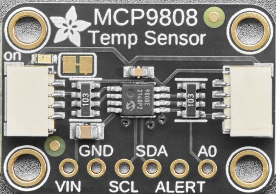
 Design with MCP9808 I2C Temperature - STEMMA QT / Qwiic in Cirkit Designer
Introduction
The MCP9808 is a high-accuracy digital temperature sensor manufactured by Adafruit. It communicates via the I2C protocol and is equipped with STEMMA QT and Qwiic connectors for seamless integration into projects. This sensor is capable of measuring temperatures with a precision of ±0.25°C (typical) and supports a wide operating temperature range from -40°C to +125°C. Its low power consumption and ease of use make it ideal for applications such as environmental monitoring, industrial systems, and IoT devices.
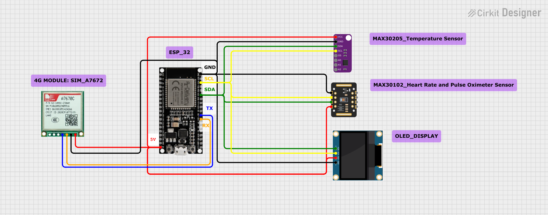
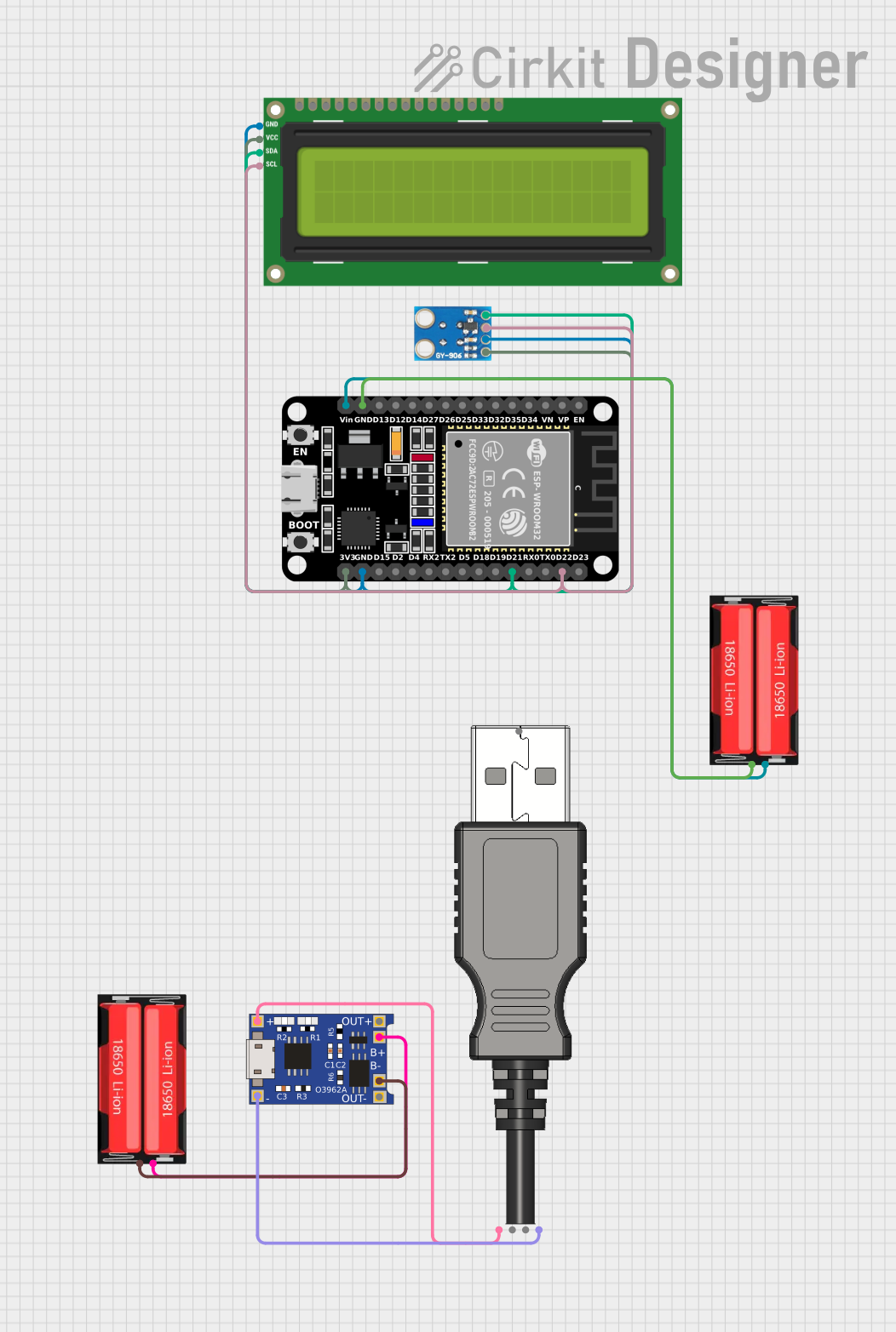
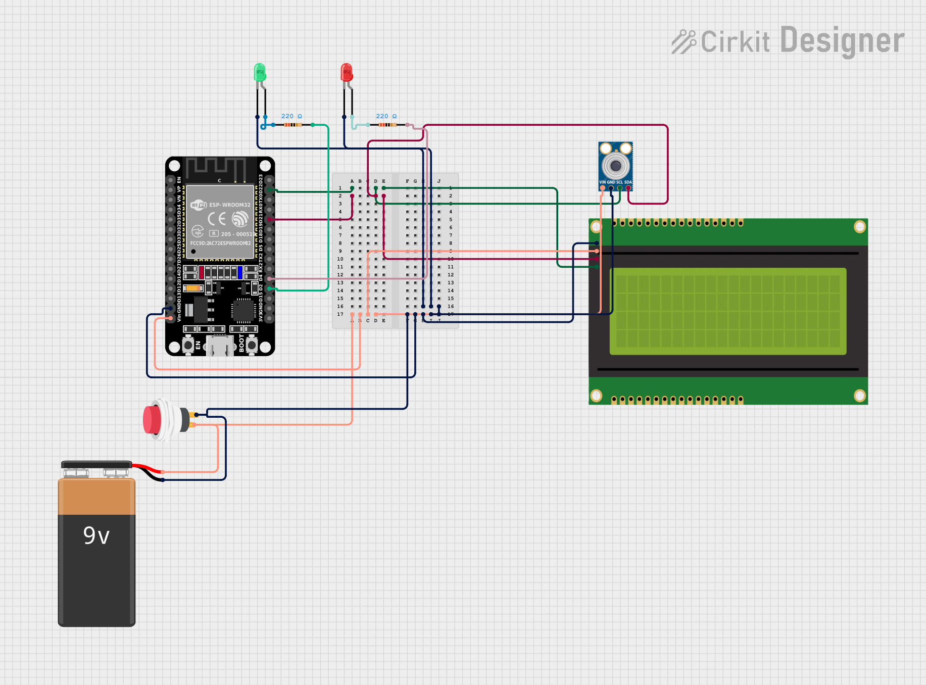
Explore Projects Built with MCP9808 I2C Temperature - STEMMA QT / Qwiic
 Open Project in Cirkit Designer
 Open Project in Cirkit Designer
 Open Project in Cirkit Designer
 Open Project in Cirkit Designer
Explore Projects Built with MCP9808 I2C Temperature - STEMMA QT / Qwiic
Open Project in Cirkit DesignerOpen Project in Cirkit DesignerOpen Project in Cirkit DesignerOpen Project in Cirkit DesignerCommon Applications:
- Weather stations and environmental monitoring
- HVAC systems
- Industrial temperature control
- IoT devices and smart home systems
- Data logging and scientific experiments
Technical Specifications
Below are the key technical details of the MCP9808 sensor:
| Parameter | Value |
|---|---|
| Operating Voltage | 2.7V to 5.5V |
| Temperature Range | -40°C to +125°C |
| Accuracy | ±0.25°C (typical) |
| Communication Protocol | I2C |
| I2C Address (Default) | 0x18 (configurable: 0x18–0x1F) |
| Current Consumption | 200 µA (typical) |
| Resolution | Configurable: 0.5°C to 0.0625°C |
| Connector Type | STEMMA QT / Qwiic |
Pin Configuration
The MCP9808 sensor has the following pinout:
| Pin Name | Description |
|---|---|
| VIN | Power input (2.7V to 5.5V) |
| GND | Ground |
| SCL | I2C clock line |
| SDA | I2C data line |
| A0, A1, A2 | Address selection pins (for I2C address setting) |
Usage Instructions
Connecting the MCP9808 to a Circuit
- Power Supply: Connect the VIN pin to a 3.3V or 5V power source and the GND pin to ground.
- I2C Communication: Connect the SCL and SDA pins to the corresponding I2C pins on your microcontroller. For an Arduino UNO:
- SCL connects to A5.
- SDA connects to A4.
- Address Configuration: Use the A0, A1, and A2 pins to set the I2C address if multiple MCP9808 sensors are used on the same bus. Leave these pins unconnected for the default address (0x18).
Important Considerations
- Ensure pull-up resistors (typically 4.7kΩ) are present on the I2C lines if not already included in your setup.
- Avoid exposing the sensor to temperatures beyond its operating range (-40°C to +125°C).
- Use the STEMMA QT or Qwiic connectors for quick and reliable connections without soldering.
Example Code for Arduino UNO
Below is an example of how to use the MCP9808 sensor with an Arduino UNO. This code reads the temperature and prints it to the Serial Monitor.
#include <Wire.h>
#include "Adafruit_MCP9808.h"

// Create an MCP9808 object
Adafruit_MCP9808 tempsensor = Adafruit_MCP9808();

void setup() {
  Serial.begin(9600); // Initialize serial communication at 9600 baud
  Serial.println("MCP9808 Temperature Sensor Test");

  // Initialize I2C communication and check sensor connection
  if (!tempsensor.begin(0x18)) {
    Serial.println("Couldn't find MCP9808! Check wiring.");
    while (1); // Halt execution if sensor is not found
  }

  // Set temperature resolution (optional)
  tempsensor.setResolution(3); // 0: 0.5°C, 1: 0.25°C, 2: 0.125°C, 3: 0.0625°C
}

void loop() {
  // Read temperature in Celsius
  float tempC = tempsensor.readTempC();

  // Print temperature to Serial Monitor
  Serial.print("Temperature: ");
  Serial.print(tempC);
  Serial.println(" °C");

  delay(1000); // Wait 1 second before next reading
}
Notes:
- Install the Adafruit MCP9808 library via the Arduino Library Manager before running the code.
- Adjust the I2C address in the
tempsensor.begin()function if the default address (0x18) is changed.
Troubleshooting and FAQs
Common Issues
Sensor Not Detected:
- Ensure the wiring is correct and matches the pinout.
- Verify that the I2C address in the code matches the sensor's configured address.
- Check for proper pull-up resistors on the I2C lines.
Incorrect Temperature Readings:
- Confirm that the sensor is operating within its specified temperature range.
- Avoid placing the sensor near heat sources or in direct sunlight.
No Output on Serial Monitor:
- Ensure the correct baud rate (9600) is selected in the Serial Monitor.
- Verify that the sensor is properly initialized in the code.
FAQs
Q: Can I use multiple MCP9808 sensors on the same I2C bus?
A: Yes, you can connect up to 8 MCP9808 sensors by configuring their I2C addresses using the A0, A1, and A2 pins.
Q: What is the default resolution of the MCP9808?
A: The default resolution is 0.25°C, but it can be adjusted to 0.5°C, 0.125°C, or 0.0625°C.
Q: Is the MCP9808 compatible with 3.3V microcontrollers?
A: Yes, the MCP9808 operates at 2.7V to 5.5V, making it compatible with both 3.3V and 5V systems.
Q: Do I need to solder the MCP9808 to use it?
A: No, the STEMMA QT and Qwiic connectors allow for solder-free connections.
By following this documentation, you can easily integrate the MCP9808 sensor into your projects for accurate and reliable temperature measurements.