Cirkit Designer
Your all-in-one circuit design IDE
Home /
Component Documentation
How to Use Yellow LED Module: Examples, Pinouts, and Specs
Introduction
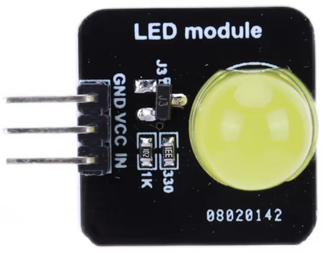
A Yellow LED Module is a light-emitting diode that emits yellow light when an electric current passes through it. It is commonly used in electronic projects for indicators and displays. This module is a versatile component that can be easily integrated into various circuits, making it a popular choice for both hobbyists and professionals.
Explore Projects Built with Yellow LED Module
Battery-Powered LED Toggle Switch Circuit
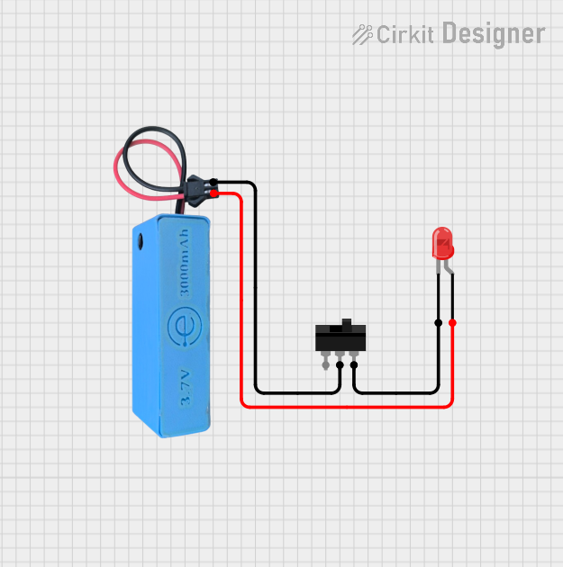
This circuit consists of a red LED, a toggle switch, and a power source. The LED is powered by a 3.7V supply from the MAHIR 1.mini module, and its illumination is controlled by the toggle switch, which connects or disconnects the LED's cathode to ground.
Battery-Powered LED Control with Relay and Switch
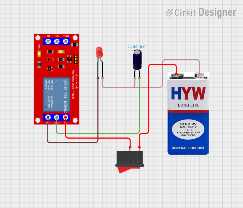
This circuit uses a 9V battery to power a red LED through a relay module, which is controlled by a rocker switch. The relay allows the LED to be turned on or off based on the position of the switch, with an electrolytic capacitor providing additional stability to the circuit.
IR Sensor-Controlled Relay with LED Indicator
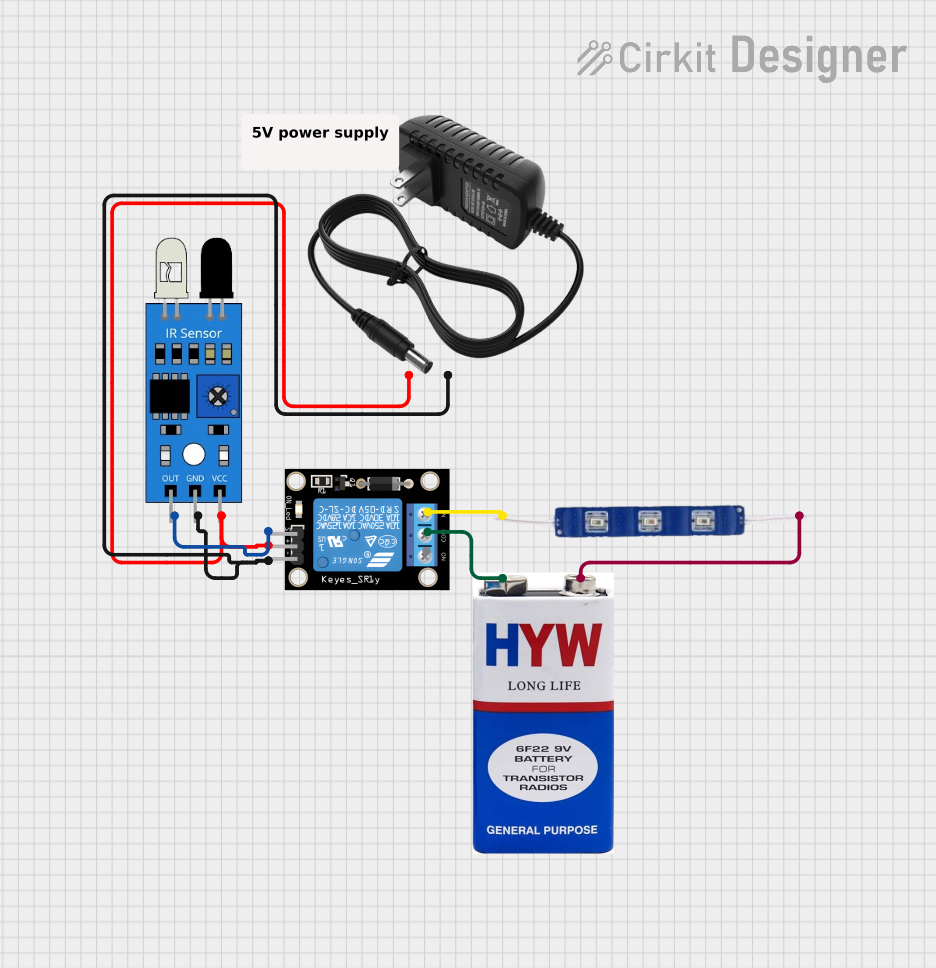
This circuit uses an IR sensor to control a relay module, which in turn switches a 12V blue LED on and off. The IR sensor output is connected to the signal input of the relay, enabling the sensor to activate the relay. The relay's normally closed (NC) contact is connected to the LED, allowing the LED to be powered by a 9V battery when the relay is not activated by the IR sensor.
Battery-Powered 4-Channel Relay Control with LED Indicators

This circuit consists of a 5V battery powering a 4-channel relay module, which controls four LEDs (red, yellow, green, and blue) through individual resistors. Each relay channel is activated by a corresponding SPST toggle switch, allowing manual control of the LEDs.
Explore Projects Built with Yellow LED Module
Battery-Powered LED Toggle Switch Circuit
This circuit consists of a red LED, a toggle switch, and a power source. The LED is powered by a 3.7V supply from the MAHIR 1.mini module, and its illumination is controlled by the toggle switch, which connects or disconnects the LED's cathode to ground.
Battery-Powered LED Control with Relay and Switch
This circuit uses a 9V battery to power a red LED through a relay module, which is controlled by a rocker switch. The relay allows the LED to be turned on or off based on the position of the switch, with an electrolytic capacitor providing additional stability to the circuit.
IR Sensor-Controlled Relay with LED Indicator
This circuit uses an IR sensor to control a relay module, which in turn switches a 12V blue LED on and off. The IR sensor output is connected to the signal input of the relay, enabling the sensor to activate the relay. The relay's normally closed (NC) contact is connected to the LED, allowing the LED to be powered by a 9V battery when the relay is not activated by the IR sensor.
Battery-Powered 4-Channel Relay Control with LED Indicators
This circuit consists of a 5V battery powering a 4-channel relay module, which controls four LEDs (red, yellow, green, and blue) through individual resistors. Each relay channel is activated by a corresponding SPST toggle switch, allowing manual control of the LEDs.
Technical Specifications
Key Technical Details
| Parameter | Value |
|---|---|
| Forward Voltage | 2.0V - 2.2V |
| Forward Current | 20mA |
| Power Rating | 44mW |
| Wavelength | 590nm - 595nm |
| Viewing Angle | 20° - 30° |
| Operating Temperature | -40°C to +85°C |
Pin Configuration and Descriptions
| Pin Number | Pin Name | Description |
|---|---|---|
| 1 | Anode | Positive terminal, connect to Vcc |
| 2 | Cathode | Negative terminal, connect to GND |
Usage Instructions
How to Use the Component in a Circuit
- Identify the Pins: The Yellow LED Module has two pins: Anode (positive) and Cathode (negative). The longer pin is typically the Anode, and the shorter pin is the Cathode.
- Connect to Power Source: Connect the Anode to the positive terminal of the power source (Vcc) and the Cathode to the negative terminal (GND).
- Use a Current-Limiting Resistor: To prevent damage to the LED, use a current-limiting resistor in series with the Anode. The value of the resistor can be calculated using Ohm's Law: [ R = \frac{V_{supply} - V_{forward}}{I_{forward}} ] For example, if using a 5V supply and the forward voltage of the LED is 2.1V, and the forward current is 20mA: [ R = \frac{5V - 2.1V}{0.02A} = 145\Omega ] A 150Ω resistor is a common choice.
Important Considerations and Best Practices
- Polarity: Ensure correct polarity when connecting the LED. Reversing the connections can damage the LED.
- Current Limiting: Always use a current-limiting resistor to prevent excessive current from flowing through the LED.
- Heat Management: While LEDs are efficient, they can still generate heat. Ensure adequate ventilation if using multiple LEDs or high currents.
Example Circuit with Arduino UNO
Circuit Diagram
Arduino UNO
+5V  ----->|---- 150Ω ----> Anode (Yellow LED)
GND  ----------------------> Cathode (Yellow LED)
Sample Code
// Define the pin for the Yellow LED
const int ledPin = 13;

void setup() {
  // Initialize the digital pin as an output
  pinMode(ledPin, OUTPUT);
}

void loop() {
  // Turn the LED on (HIGH is the voltage level)
  digitalWrite(ledPin, HIGH);
  delay(1000); // Wait for a second

  // Turn the LED off by making the voltage LOW
  digitalWrite(ledPin, LOW);
  delay(1000); // Wait for a second
}
Troubleshooting and FAQs
Common Issues Users Might Face
LED Not Lighting Up:
- Check Polarity: Ensure the Anode is connected to the positive terminal and the Cathode to the negative terminal.
- Check Connections: Verify all connections are secure and correct.
- Check Resistor: Ensure a current-limiting resistor is used and is of the correct value.
LED Flickering:
- Power Supply Stability: Ensure the power supply is stable and not fluctuating.
- Loose Connections: Check for any loose or intermittent connections.
LED Dim:
- Insufficient Current: Ensure the current-limiting resistor is not too high, reducing the current below the required level.
- Power Supply Voltage: Verify the power supply voltage is adequate for the LED's forward voltage.
Solutions and Tips for Troubleshooting
- Double-Check Connections: Always double-check your circuit connections before powering up.
- Use a Multimeter: Use a multimeter to check the voltage and current in the circuit to ensure they are within the specified range.
- Test with a Known Good LED: If troubleshooting fails, test with a known good LED to rule out a faulty component.
By following this documentation, users should be able to effectively integrate and troubleshoot the Yellow LED Module in their electronic projects.