How to Use motor driver ic proteus: Examples, Pinouts, and Specs
Introduction
The L293D Motor Driver IC by Tescity is a versatile and widely used integrated circuit designed for controlling the operation of DC motors and stepper motors. In the Proteus simulation environment, this IC is used to simulate motor control in electronic designs, enabling users to test and validate motor control circuits before physical implementation. The L293D allows for bidirectional control of motors, as well as speed regulation through Pulse Width Modulation (PWM).
Explore Projects Built with motor driver ic proteus
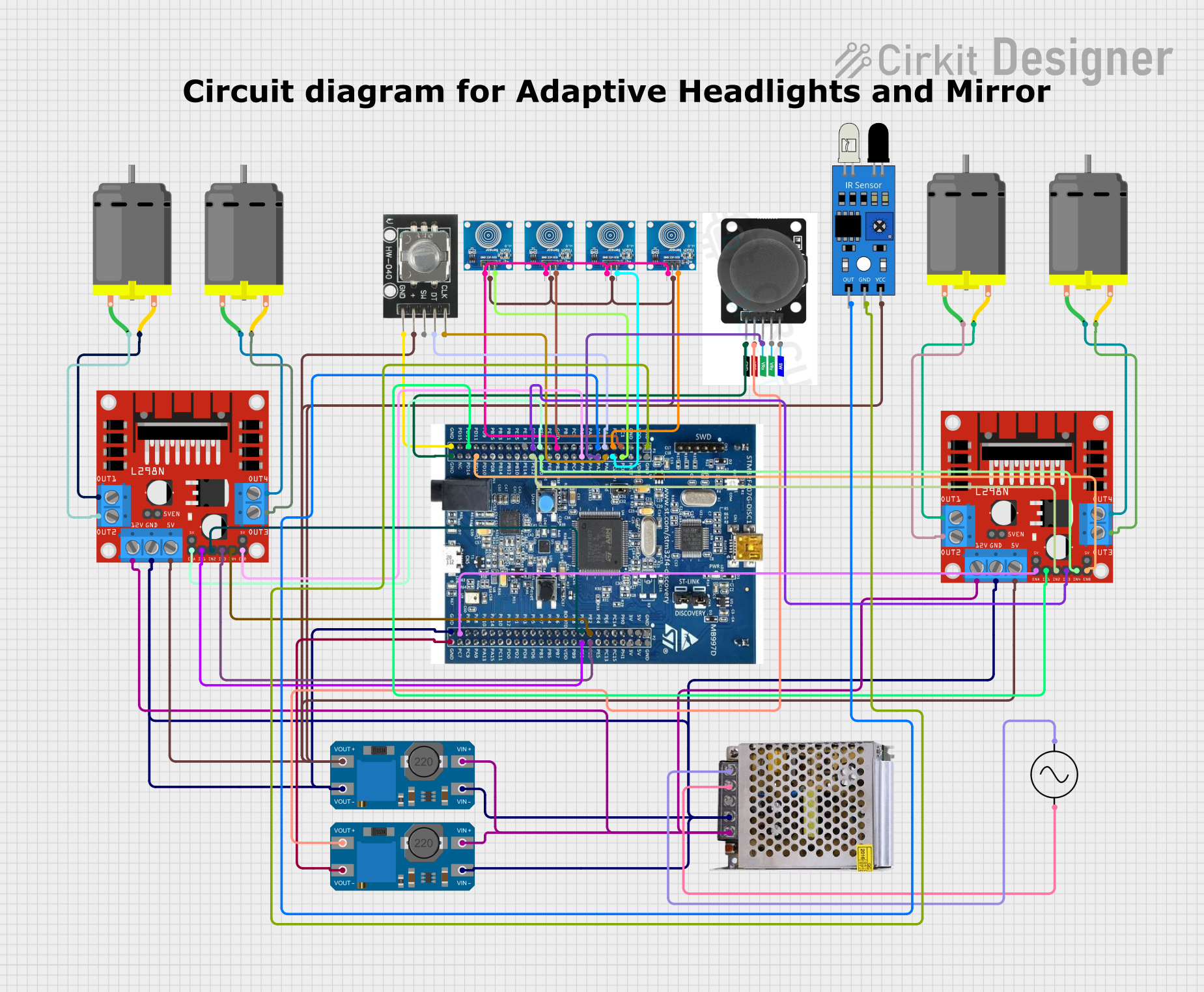
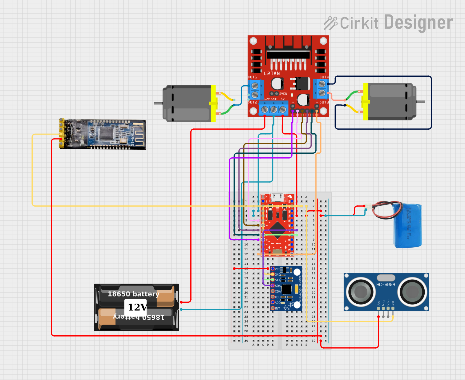
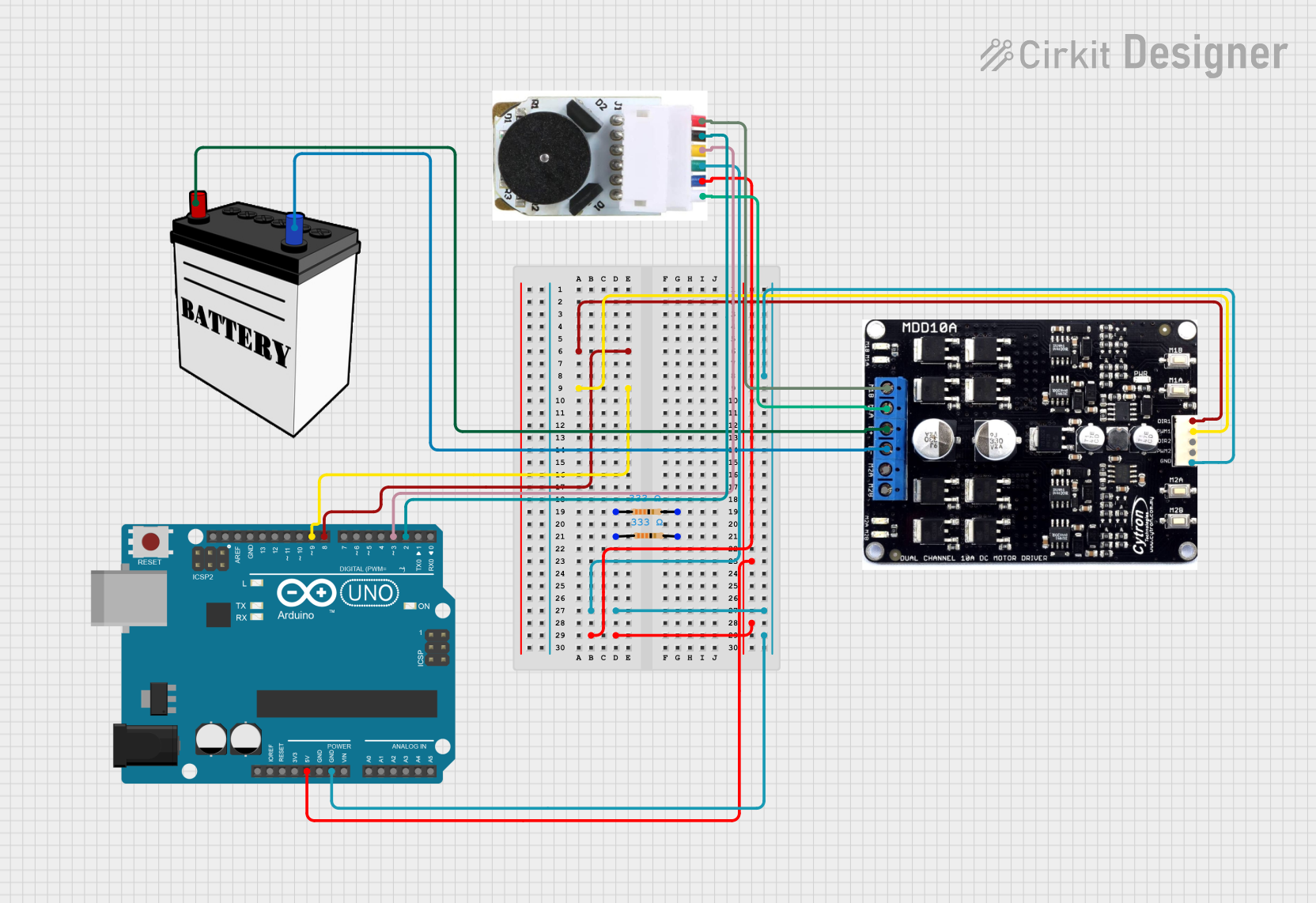

Explore Projects Built with motor driver ic proteus
Common Applications and Use Cases
- Robotics and automation systems
- Motorized conveyor belts
- Remote-controlled vehicles
- Industrial machinery
- Educational projects and simulations
Technical Specifications
Key Technical Details
- Manufacturer Part ID: L293D
- Operating Voltage: 4.5V to 36V
- Output Current (per channel): 600mA (continuous), 1.2A (peak)
- Number of Channels: 2 (dual H-bridge configuration)
- Logic Input Voltage: 0V to 7V
- Enable Pins for PWM Control: Yes
- Thermal Shutdown Protection: Yes
- Simulated Environment: Proteus Design Suite
Pin Configuration and Descriptions
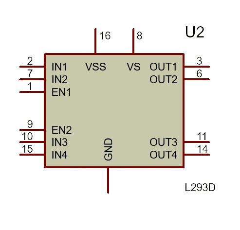
The L293D IC has 16 pins, with the following configuration:
| Pin Number | Pin Name | Description |
|---|---|---|
| 1 | Enable 1 (EN1) | Enables or disables motor 1 (connect to PWM for speed control). |
| 2 | Input 1 (IN1) | Logic input to control motor 1 direction (high or low). |
| 3 | Output 1 (OUT1) | Output connected to one terminal of motor 1. |
| 4 | Ground (GND) | Ground connection. |
| 5 | Ground (GND) | Ground connection. |
| 6 | Output 2 (OUT2) | Output connected to the other terminal of motor 1. |
| 7 | Input 2 (IN2) | Logic input to control motor 1 direction (high or low). |
| 8 | Vcc2 (Motor Vcc) | Supply voltage for motors (4.5V to 36V). |
| 9 | Enable 2 (EN2) | Enables or disables motor 2 (connect to PWM for speed control). |
| 10 | Input 3 (IN3) | Logic input to control motor 2 direction (high or low). |
| 11 | Output 3 (OUT3) | Output connected to one terminal of motor 2. |
| 12 | Ground (GND) | Ground connection. |
| 13 | Ground (GND) | Ground connection. |
| 14 | Output 4 (OUT4) | Output connected to the other terminal of motor 2. |
| 15 | Input 4 (IN4) | Logic input to control motor 2 direction (high or low). |
| 16 | Vcc1 (Logic Vcc) | Supply voltage for the logic circuit (5V). |
Usage Instructions
How to Use the L293D in a Circuit
Power Connections:
- Connect Vcc1 (Pin 16) to a 5V power supply for the logic circuit.
- Connect Vcc2 (Pin 8) to the motor power supply (4.5V to 36V, depending on the motor).
- Connect all GND pins (Pins 4, 5, 12, 13) to the ground of the power supply.
Motor Connections:
- Connect the motor terminals to the output pins (OUT1, OUT2 for motor 1; OUT3, OUT4 for motor 2).
Control Logic:
- Use the input pins (IN1, IN2, IN3, IN4) to control the direction of the motors.
- Use the enable pins (EN1, EN2) to enable or disable the motors. For speed control, connect these pins to a PWM signal.
Direction Control:
- Set the input pins high or low to control the direction of the motor. For example:
- IN1 = HIGH, IN2 = LOW: Motor 1 rotates in one direction.
- IN1 = LOW, IN2 = HIGH: Motor 1 rotates in the opposite direction.
- Set the input pins high or low to control the direction of the motor. For example:
Simulation in Proteus:
- Add the L293D IC to your Proteus schematic.
- Connect the inputs, outputs, and power pins as described above.
- Use virtual components (e.g., DC motors, power supplies, and microcontrollers) to simulate the circuit.
Important Considerations and Best Practices
- Ensure that the motor power supply voltage (Vcc2) matches the motor's operating voltage.
- Use decoupling capacitors near the power supply pins to reduce noise.
- Avoid exceeding the maximum current rating of 600mA per channel to prevent damage.
- For PWM speed control, ensure the frequency is within the motor's response range.
- In Proteus, verify the connections and logic levels before running the simulation.
Example Code for Arduino UNO
Below is an example of how to control a DC motor using the L293D IC and an Arduino UNO:
// Define motor control pins
const int ENA = 9;  // Enable pin for motor 1 (connected to PWM)
const int IN1 = 7;  // Input 1 for motor 1
const int IN2 = 6;  // Input 2 for motor 1

void setup() {
  // Set motor control pins as outputs
  pinMode(ENA, OUTPUT);
  pinMode(IN1, OUTPUT);
  pinMode(IN2, OUTPUT);
}

void loop() {
  // Rotate motor in one direction
  digitalWrite(IN1, HIGH);  // Set IN1 high
  digitalWrite(IN2, LOW);   // Set IN2 low
  analogWrite(ENA, 128);    // Set speed to 50% (PWM value: 128 out of 255)
  delay(2000);              // Run for 2 seconds

  // Stop the motor
  digitalWrite(IN1, LOW);   // Set IN1 low
  digitalWrite(IN2, LOW);   // Set IN2 low
  delay(1000);              // Wait for 1 second

  // Rotate motor in the opposite direction
  digitalWrite(IN1, LOW);   // Set IN1 low
  digitalWrite(IN2, HIGH);  // Set IN2 high
  analogWrite(ENA, 200);    // Set speed to ~78% (PWM value: 200 out of 255)
  delay(2000);              // Run for 2 seconds

  // Stop the motor
  digitalWrite(IN1, LOW);   // Set IN1 low
  digitalWrite(IN2, LOW);   // Set IN2 low
  delay(1000);              // Wait for 1 second
}
Troubleshooting and FAQs
Common Issues and Solutions
Motor Not Spinning:
- Check the power supply connections to Vcc1 and Vcc2.
- Ensure the enable pin (EN1 or EN2) is set high or connected to a PWM signal.
- Verify the input logic levels (IN1, IN2, etc.) are correctly set.
Motor Spins in the Wrong Direction:
- Reverse the logic levels of the input pins (e.g., swap HIGH and LOW for IN1 and IN2).
Overheating of the IC:
- Ensure the current drawn by the motor does not exceed 600mA per channel.
- Use a heat sink or cooling mechanism if necessary.
Simulation Errors in Proteus:
- Double-check the connections in the schematic.
- Ensure the motor and power supply components are correctly configured in Proteus.
FAQs
Can I control two motors simultaneously? Yes, the L293D can control two DC motors independently using its dual H-bridge configuration.
What is the purpose of the enable pins? The enable pins (EN1 and EN2) are used to enable or disable the motors. They can also be connected to a PWM signal for speed control.
Can I use the L293D with a stepper motor? Yes, the L293D can control a stepper motor by driving its coils in the correct sequence.
Is the L293D suitable for high-power motors? No, the L293D is designed for low- to medium-power motors. For high-power motors, consider using a motor driver with a higher current rating.