Cirkit Designer Logo
Cirkit Designer
Your all-in-one circuit design IDE
Home / 
Component Documentation

How to Use VL53L5CX-SATEL: Examples, Pinouts, and Specs

Image of VL53L5CX-SATEL
Cirkit Designer LogoDesign with VL53L5CX-SATEL in Cirkit Designer

Introduction

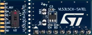
The VL53L5CX-SATEL is a state-of-the-art time-of-flight (ToF) distance sensor module developed by STMicroelectronics. It leverages advanced laser technology to measure distances with high precision and speed. The sensor features a wide field of view (FoV) and supports multi-target detection, making it ideal for applications requiring spatial awareness and object detection.

Explore Projects Built with VL53L5CX-SATEL

Use Cirkit Designer to design, explore, and prototype these projects online. Some projects support real-time simulation. Click "Open Project" to start designing instantly!
Arduino UNO with A9G GSM/GPRS and Dual VL53L1X Distance Sensors
Image of TED CIRCUIT : A project utilizing VL53L5CX-SATEL in a practical application
This circuit features an Arduino UNO microcontroller interfaced with an A9G GSM/GPRS+GPS/BDS module and two VL53L1X time-of-flight distance sensors. The A9G module is connected to the Arduino via serial communication for GPS and GSM functionalities, while both VL53L1X sensors are connected through I2C with shared SDA and SCL lines and individual SHUT pins for selective sensor activation. The Arduino is programmed to control these peripherals, although the specific functionality is not detailed in the provided code.
Cirkit Designer LogoOpen Project in Cirkit Designer
Cellular-Enabled IoT Device with Real-Time Clock and Power Management
Image of LRCM PHASE 2 BASIC: A project utilizing VL53L5CX-SATEL in a practical application
This circuit features a LilyGo-SIM7000G module for cellular communication and GPS functionality, interfaced with an RTC DS3231 for real-time clock capabilities. It includes voltage sensing through two voltage sensor modules, and uses an 8-channel opto-coupler for isolating different parts of the circuit. Power management is handled by a buck converter connected to a DC power source and batteries, with a fuse for protection and a rocker switch for on/off control. Additionally, there's an LED for indication purposes.
Cirkit Designer LogoOpen Project in Cirkit Designer
Lilygo 7670e-Based Smart Interface with LCD Display and Keypad
Image of Paower: A project utilizing VL53L5CX-SATEL in a practical application
This circuit features a Lilygo 7670e microcontroller interfaced with a 16x2 I2C LCD for display, a 4X4 membrane matrix keypad for input, and an arcade button for additional control. It also includes a 4G antenna and a GPS antenna for communication and location tracking capabilities.
Cirkit Designer LogoOpen Project in Cirkit Designer
Satellite-Based Timing and Navigation System with SDR and Atomic Clock Synchronization
Image of GPS 시스템 측정 구성도_Confirm: A project utilizing VL53L5CX-SATEL in a practical application
This circuit appears to be a complex system involving power supply management, GPS and timing synchronization, and data communication. It includes a SI-TEX G1 Satellite Compass for GPS data, an XHTF1021 Atomic Rubidium Clock for precise timing, and Ettus USRP B200 units for software-defined radio communication. Power is supplied through various SMPS units and distributed via terminal blocks and DC jacks. Data communication is facilitated by Beelink MINI S12 N95 computers, RS232 splitters, and a 1000BASE-T Media Converter for network connectivity. RF Directional Couplers are used to interface antennas with the USRP units, and the entire system is likely contained within cases for protection and organization.
Cirkit Designer LogoOpen Project in Cirkit Designer

Explore Projects Built with VL53L5CX-SATEL

Use Cirkit Designer to design, explore, and prototype these projects online. Some projects support real-time simulation. Click "Open Project" to start designing instantly!
Image of TED CIRCUIT : A project utilizing VL53L5CX-SATEL in a practical application
Arduino UNO with A9G GSM/GPRS and Dual VL53L1X Distance Sensors
This circuit features an Arduino UNO microcontroller interfaced with an A9G GSM/GPRS+GPS/BDS module and two VL53L1X time-of-flight distance sensors. The A9G module is connected to the Arduino via serial communication for GPS and GSM functionalities, while both VL53L1X sensors are connected through I2C with shared SDA and SCL lines and individual SHUT pins for selective sensor activation. The Arduino is programmed to control these peripherals, although the specific functionality is not detailed in the provided code.
Cirkit Designer LogoOpen Project in Cirkit Designer
Image of LRCM PHASE 2 BASIC: A project utilizing VL53L5CX-SATEL in a practical application
Cellular-Enabled IoT Device with Real-Time Clock and Power Management
This circuit features a LilyGo-SIM7000G module for cellular communication and GPS functionality, interfaced with an RTC DS3231 for real-time clock capabilities. It includes voltage sensing through two voltage sensor modules, and uses an 8-channel opto-coupler for isolating different parts of the circuit. Power management is handled by a buck converter connected to a DC power source and batteries, with a fuse for protection and a rocker switch for on/off control. Additionally, there's an LED for indication purposes.
Cirkit Designer LogoOpen Project in Cirkit Designer
Image of Paower: A project utilizing VL53L5CX-SATEL in a practical application
Lilygo 7670e-Based Smart Interface with LCD Display and Keypad
This circuit features a Lilygo 7670e microcontroller interfaced with a 16x2 I2C LCD for display, a 4X4 membrane matrix keypad for input, and an arcade button for additional control. It also includes a 4G antenna and a GPS antenna for communication and location tracking capabilities.
Cirkit Designer LogoOpen Project in Cirkit Designer
Image of GPS 시스템 측정 구성도_Confirm: A project utilizing VL53L5CX-SATEL in a practical application
Satellite-Based Timing and Navigation System with SDR and Atomic Clock Synchronization
This circuit appears to be a complex system involving power supply management, GPS and timing synchronization, and data communication. It includes a SI-TEX G1 Satellite Compass for GPS data, an XHTF1021 Atomic Rubidium Clock for precise timing, and Ettus USRP B200 units for software-defined radio communication. Power is supplied through various SMPS units and distributed via terminal blocks and DC jacks. Data communication is facilitated by Beelink MINI S12 N95 computers, RS232 splitters, and a 1000BASE-T Media Converter for network connectivity. RF Directional Couplers are used to interface antennas with the USRP units, and the entire system is likely contained within cases for protection and organization.
Cirkit Designer LogoOpen Project in Cirkit Designer

Common Applications and Use Cases

  • Robotics: Obstacle detection, navigation, and mapping.
  • Automation: Proximity sensing and object tracking in industrial systems.
  • Smart Devices: Gesture recognition, presence detection, and environmental monitoring.
  • Drones: Altitude measurement and collision avoidance.
  • Consumer Electronics: Smart home devices and gaming peripherals.

Technical Specifications

The following table outlines the key technical details of the VL53L5CX-SATEL:

Parameter Value
Manufacturer STMicroelectronics
Part Number VL53L5CX
Measurement Range 0.1 m to 4 m (typical, depending on target reflectance and conditions)
Field of View (FoV) 45° x 45°
Resolution 8x8 zones (64 zones)
Accuracy ±1 cm (typical, depending on conditions)
Operating Voltage 2.8 V to 3.3 V
Interface I²C (up to 1 MHz)
Power Consumption 5 mW (typical in low-power mode)
Operating Temperature Range -30°C to +85°C
Dimensions 6.4 mm x 3.0 mm x 1.5 mm

Pin Configuration and Descriptions

The VL53L5CX-SATEL module has the following pinout:

Pin Name Type Description
VIN Power Input voltage (2.8 V to 3.3 V). Powers the sensor.
GND Ground Ground connection.
SDA I²C Data Serial data line for I²C communication.
SCL I²C Clock Serial clock line for I²C communication.
GPIO1 Digital I/O General-purpose I/O pin (can be used for interrupts or other functions).
GPIO2 Digital I/O General-purpose I/O pin (optional, configurable).
XSHUT Input Shutdown pin. Pull low to put the sensor in shutdown mode.
INT Output Interrupt pin. Indicates when data is ready or an event has occurred.

Usage Instructions

How to Use the VL53L5CX-SATEL in a Circuit

  1. Power the Sensor: Connect the VIN pin to a 3.3 V power source and GND to ground.
  2. I²C Communication: Connect the SDA and SCL pins to the corresponding I²C pins on your microcontroller (e.g., Arduino UNO).
  3. Optional Pins:
    • Use the XSHUT pin to control the sensor's power state.
    • Configure the GPIO1 and GPIO2 pins for additional functionality if needed.
  4. Pull-Up Resistors: Ensure that the I²C lines (SDA and SCL) have appropriate pull-up resistors (typically 4.7 kΩ).

Important Considerations and Best Practices

  • Ambient Light: Avoid direct exposure to strong ambient light sources, as they may affect measurement accuracy.
  • Reflective Surfaces: Highly reflective or transparent surfaces may cause inaccurate readings.
  • Mounting: Ensure the sensor is mounted securely and aligned properly for accurate distance measurements.
  • I²C Address: The default I²C address is 0x52. Ensure no address conflicts if multiple devices are on the same bus.

Example Code for Arduino UNO

Below is an example of how to interface the VL53L5CX-SATEL with an Arduino UNO using the I²C protocol:

#include <Wire.h>
#include <VL53L5CX.h> // Include the VL53L5CX library (install via Arduino Library Manager)

// Create an instance of the VL53L5CX sensor
VL53L5CX sensor;

void setup() {
  Serial.begin(9600); // Initialize serial communication for debugging
  Wire.begin();       // Initialize I²C communication

  // Initialize the VL53L5CX sensor
  if (!sensor.begin()) {
    Serial.println("Failed to initialize VL53L5CX sensor!");
    while (1); // Halt execution if initialization fails
  }

  Serial.println("VL53L5CX sensor initialized successfully.");
}

void loop() {
  // Read distance data from the sensor
  uint16_t distances[64]; // Array to store distances for all 64 zones
  if (sensor.getDistances(distances)) {
    Serial.println("Distance readings (in mm):");
    for (int i = 0; i < 64; i++) {
      Serial.print(distances[i]);
      Serial.print(" ");
      if ((i + 1) % 8 == 0) Serial.println(); // Print 8 zones per line
    }
    Serial.println();
  } else {
    Serial.println("Failed to read distances.");
  }

  delay(500); // Wait 500 ms before the next reading
}

Notes:

  • Install the VL53L5CX Arduino library from the Arduino Library Manager before running the code.
  • Ensure the I²C pull-up resistors are in place for proper communication.

Troubleshooting and FAQs

Common Issues and Solutions

  1. Sensor Not Detected on I²C Bus:

    • Ensure the sensor is powered correctly (check VIN and GND connections).
    • Verify the I²C address (0x52) and ensure no conflicts with other devices.
    • Check for proper pull-up resistors on the SDA and SCL lines.
  2. Inaccurate Distance Measurements:

    • Ensure the sensor is not exposed to strong ambient light or reflective surfaces.
    • Verify that the target is within the sensor's measurement range (0.1 m to 4 m).
  3. Sensor Initialization Fails:

    • Confirm that the XSHUT pin is not held low during initialization.
    • Check the wiring and ensure the I²C lines are connected properly.
  4. Interference from Multiple Sensors:

    • If using multiple VL53L5CX sensors, assign unique I²C addresses to each sensor.

FAQs

Q1: Can the VL53L5CX-SATEL detect multiple objects simultaneously?
Yes, the sensor supports multi-target detection and can measure distances for up to 64 zones within its field of view.

Q2: What is the maximum range of the sensor?
The typical maximum range is 4 meters, depending on the target's reflectance and environmental conditions.

Q3: Can the sensor operate in outdoor environments?
Yes, but performance may be affected by strong sunlight or extreme temperatures. Ensure the sensor is shielded from direct sunlight for optimal results.

Q4: Is the VL53L5CX-SATEL compatible with 5V microcontrollers?
The sensor operates at 3.3V logic levels. Use a level shifter if interfacing with a 5V microcontroller like the Arduino UNO.

Q5: How can I reduce power consumption?
Use the XSHUT pin to put the sensor into shutdown mode when not in use, or configure it to operate in low-power mode.