How to Use Arduino GIGA R1: Examples, Pinouts, and Specs
Introduction
The Arduino GIGA R1 WiFi is a high-performance microcontroller board designed for advanced projects and applications. Powered by a 32-bit ARM Cortex-M7 processor, it offers exceptional computational power, making it ideal for demanding tasks such as robotics, IoT, machine learning, and multimedia processing. The board also features a secondary ARM Cortex-M4 core, enabling real-time operations and multitasking.
With its extensive I/O capabilities, built-in WiFi and Bluetooth connectivity, and compatibility with a wide range of sensors and modules, the GIGA R1 WiFi is a versatile platform for both hobbyists and professionals.
Explore Projects Built with Arduino GIGA R1
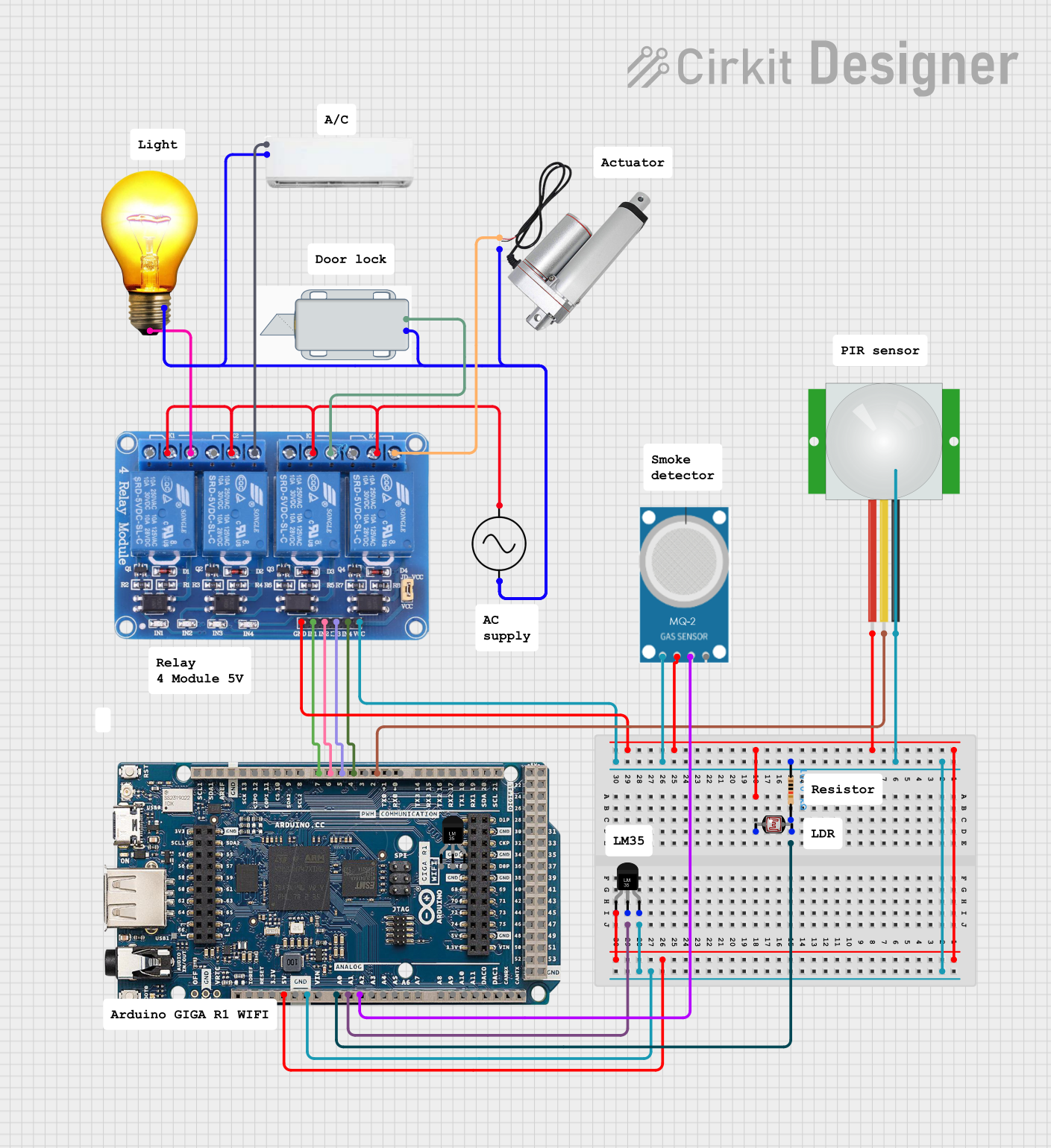
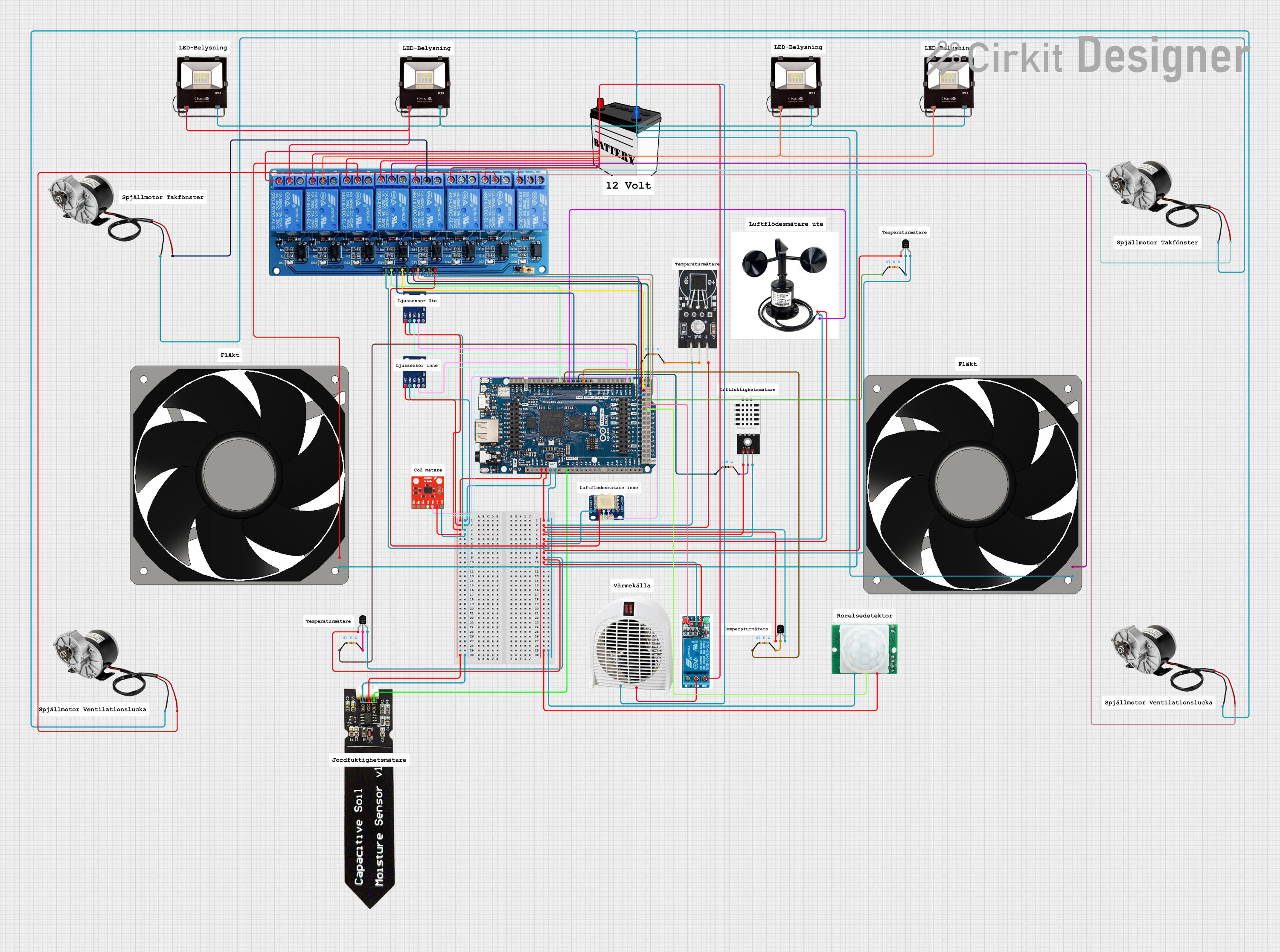
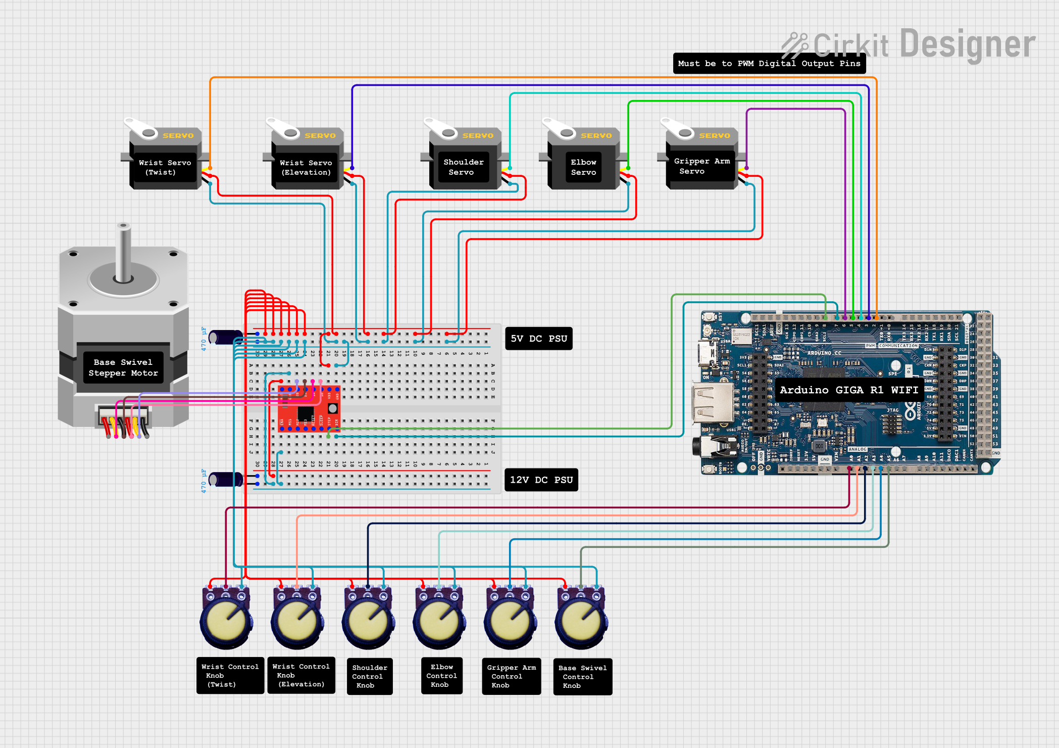
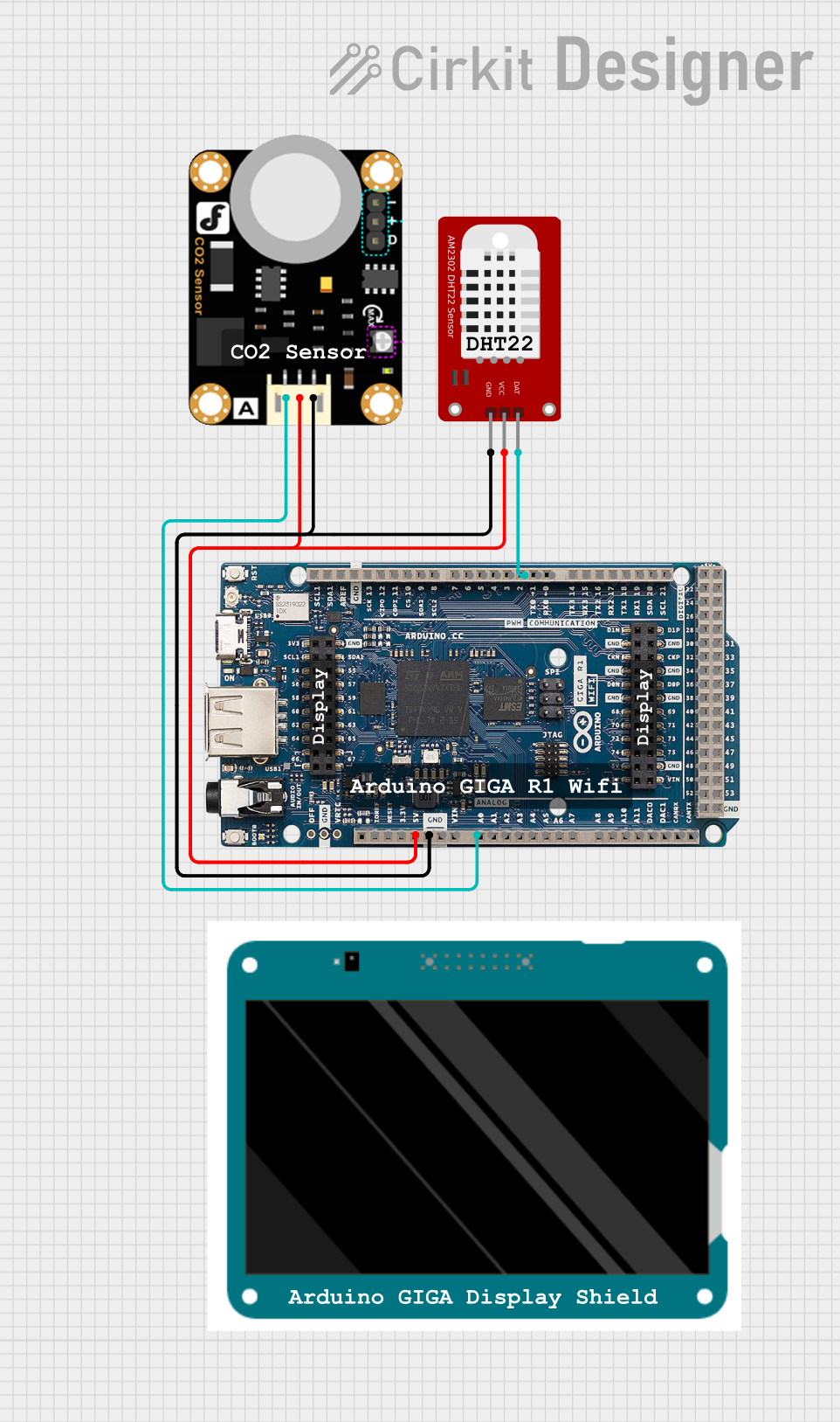
Explore Projects Built with Arduino GIGA R1
Common Applications
- Robotics and automation systems
- IoT (Internet of Things) devices and smart home applications
- Machine learning and AI-based projects
- Multimedia processing (e.g., audio and video applications)
- Data acquisition and real-time monitoring systems
Technical Specifications
Key Technical Details
| Specification | Value |
|---|---|
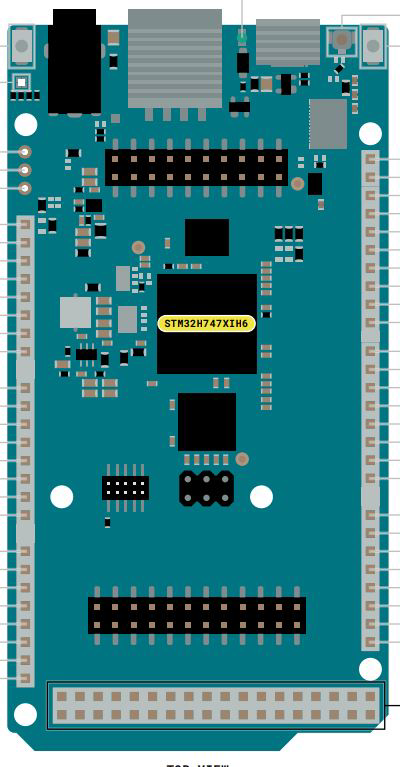
| Microcontroller | STM32H747XI (ARM Cortex-M7 @ 480 MHz + ARM Cortex-M4 @ 240 MHz) |
| Operating Voltage | 3.3V |
| Input Voltage (VIN) | 7-12V |
| Digital I/O Pins | 76 (12 PWM outputs) |
| Analog Input Pins | 12 (ADC resolution: 12-bit) |
| Analog Output Pins | 2 (DAC resolution: 12-bit) |
| Flash Memory | 8 MB |
| SRAM | 1 MB |
| EEPROM | None (emulated in Flash) |
| Communication Interfaces | UART, I2C, SPI, CAN, USB-C (Host/Device) |
| Connectivity | WiFi (802.11 b/g/n), Bluetooth 5.1 |
| Dimensions | 102 x 25 mm |
| Weight | 25 g |
Pin Configuration and Descriptions
The Arduino GIGA R1 WiFi features a rich set of pins for various functionalities. Below is a summary of the pin configuration:
Power Pins
| Pin Name | Description |
|---|---|
| VIN | Input voltage to the board (7-12V) |
| 3.3V | Regulated 3.3V output |
| 5V | Regulated 5V output |
| GND | Ground |
Digital I/O Pins
| Pin Range | Description |
|---|---|
| D0-D53 | General-purpose digital I/O pins |
| PWM Pins | D2-D13, D44-D53 (PWM capable) |
Analog Pins
| Pin Name | Description |
|---|---|
| A0-A11 | Analog input pins (12-bit ADC) |
| DAC0, DAC1 | Analog output pins (12-bit DAC) |
Communication Pins
| Pin Name | Description |
|---|---|
| TX/RX | UART communication |
| SDA/SCL | I2C communication |
| MOSI/MISO/SCK | SPI communication |
| CANRX/CANTX | CAN bus communication |
Special Pins
| Pin Name | Description |
|---|---|
| RESET | Resets the microcontroller |
| USB-C | USB Host/Device interface |
| BOOT0 | Bootloader mode selection |
Usage Instructions
How to Use the Arduino GIGA R1 WiFi in a Circuit
Powering the Board:
- Use the USB-C port for powering and programming the board.
- Alternatively, supply 7-12V to the VIN pin for standalone operation.
Connecting Peripherals:
- Use the digital and analog pins to connect sensors, actuators, and other peripherals.
- For communication, utilize the UART, I2C, SPI, or CAN interfaces as needed.
Programming the Board:
- Install the Arduino IDE and add the GIGA R1 WiFi board via the Boards Manager.
- Select the correct board and port in the IDE, then upload your sketch.
Using WiFi and Bluetooth:
- The board includes built-in WiFi and Bluetooth capabilities. Use the
WiFiandBluetoothSeriallibraries to enable wireless communication.
- The board includes built-in WiFi and Bluetooth capabilities. Use the
Important Considerations and Best Practices
- Voltage Levels: The board operates at 3.3V logic levels. Ensure connected devices are compatible or use level shifters.
- Power Supply: Avoid exceeding the recommended input voltage range (7-12V) to prevent damage.
- Multitasking: Leverage the dual-core architecture for real-time and computationally intensive tasks.
- Heat Management: For prolonged high-performance operations, consider adding a heatsink to the microcontroller.
Example Code: Blinking an LED
The following example demonstrates how to blink an LED connected to pin D13:
// Define the LED pin
const int ledPin = 13;

void setup() {
  // Set the LED pin as an output
  pinMode(ledPin, OUTPUT);
}

void loop() {
  // Turn the LED on
  digitalWrite(ledPin, HIGH);
  delay(1000); // Wait for 1 second

  // Turn the LED off
  digitalWrite(ledPin, LOW);
  delay(1000); // Wait for 1 second
}
Example Code: Connecting to WiFi
The following example shows how to connect the GIGA R1 WiFi to a WiFi network:
#include <WiFi.h>

// Replace with your network credentials
const char* ssid = "Your_SSID";
const char* password = "Your_PASSWORD";

void setup() {
  Serial.begin(115200); // Initialize serial communication
  Serial.println("Connecting to WiFi...");

  // Connect to WiFi
  WiFi.begin(ssid, password);

  // Wait until connected
  while (WiFi.status() != WL_CONNECTED) {
    delay(1000);
    Serial.println("Connecting...");
  }

  // Print the IP address once connected
  Serial.println("Connected to WiFi!");
  Serial.print("IP Address: ");
  Serial.println(WiFi.localIP());
}

void loop() {
  // Add your main code here
}
Troubleshooting and FAQs
Common Issues and Solutions
The board is not detected by the Arduino IDE:
- Ensure the correct USB driver is installed.
- Check that the USB cable is functional and supports data transfer.
- Verify that the correct board and port are selected in the IDE.
WiFi connection fails:
- Double-check the SSID and password.
- Ensure the WiFi network is operational and within range.
- Restart the board and try reconnecting.
Sketch upload fails:
- Press the RESET button on the board and try uploading again.
- Ensure no other application is using the USB port.
Overheating during operation:
- Reduce the workload or add a heatsink to the microcontroller.
- Ensure proper ventilation around the board.
FAQs
Q: Can I use 5V sensors with the GIGA R1 WiFi?
A: The board operates at 3.3V logic levels. Use a level shifter to interface with 5V sensors.
Q: How do I use the dual-core functionality?
A: The Arduino IDE provides support for dual-core programming. Refer to the STM32H747XI documentation for advanced usage.
Q: Is the GIGA R1 WiFi compatible with Arduino shields?
A: Yes, it is compatible with most Arduino shields, but ensure voltage compatibility.
Q: Can I use the board for battery-powered applications?
A: Yes, you can power the board using a battery connected to the VIN pin, but ensure the voltage is within the 7-12V range.
This concludes the documentation for the Arduino GIGA R1 WiFi. For further details, refer to the official Arduino website or community forums.