Cirkit Designer
Your all-in-one circuit design IDE
Home /
Component Documentation
How to Use LilyPad Reed Switch: Examples, Pinouts, and Specs

Introduction
The LilyPad Reed Switch is a magnetic switch designed to be easily integrated into e-textiles and wearable projects. It is part of the LilyPad Arduino ecosystem, a set of sewable electronic components that can be used to build interactive garments and accessories. The reed switch activates when a magnetic field is applied, making it ideal for creating switches in clothing without the need for hard mechanical parts.
Explore Projects Built with LilyPad Reed Switch
Battery-Powered Smart Light with Wemos D1 Mini and Reed Switches
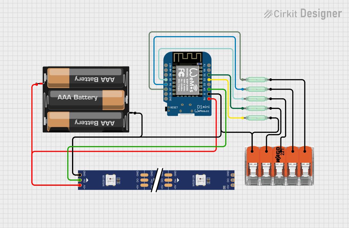
This circuit uses a Wemos D1 Mini microcontroller to monitor the state of multiple reed switches and control a WS2812 RGB LED strip. The microcontroller is powered by a 3xAA battery pack, and the reed switches are used to trigger different actions or lighting patterns on the LED strip.
Wi-Fi Enabled Smart Lid Status Monitor with NodeMCU and RGB LED
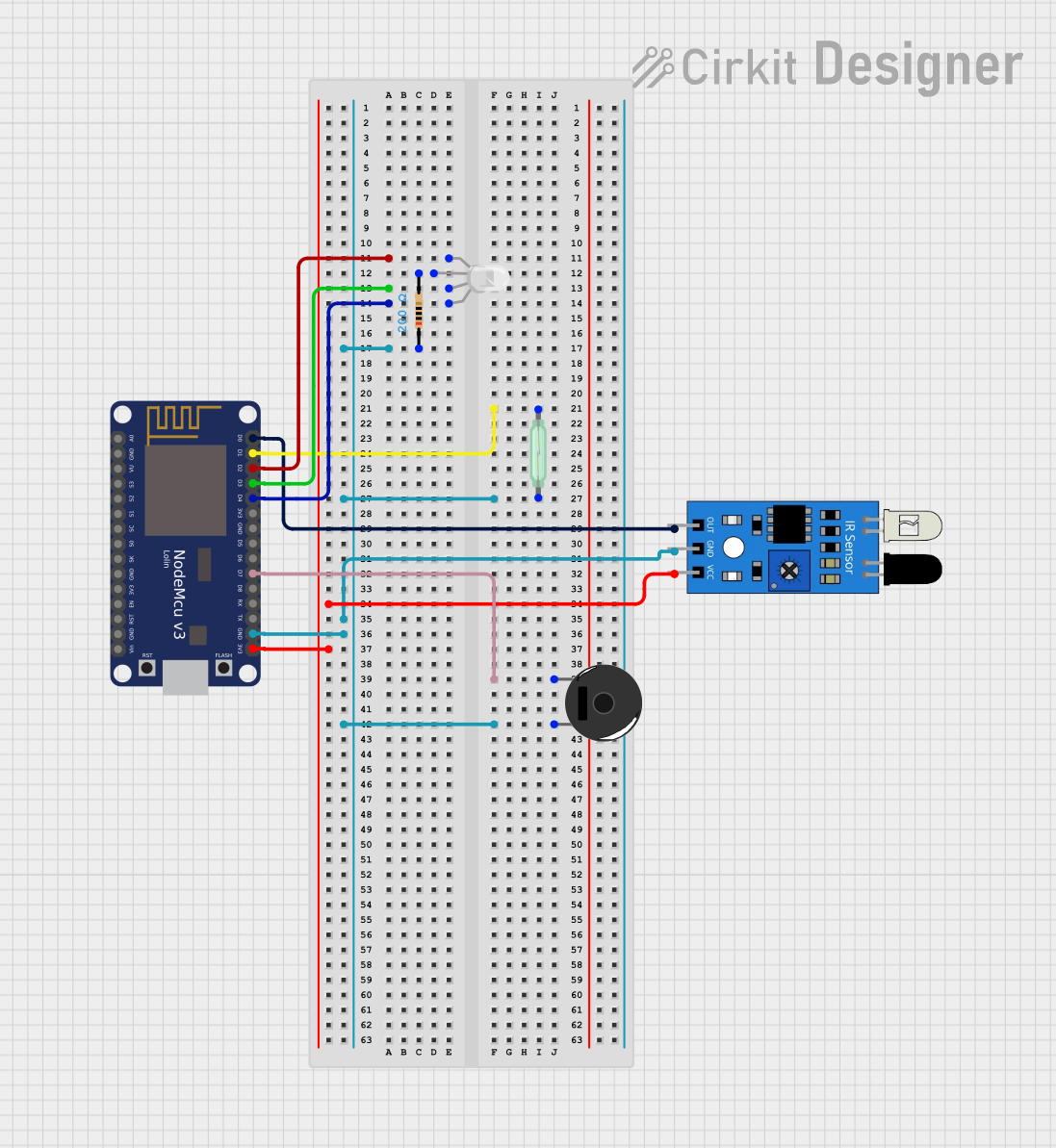
This circuit uses a NodeMCU V3 ESP8266 microcontroller to monitor the state of a reed switch and an IR sensor, and control an RGB LED and a piezo buzzer. The microcontroller reads the reed switch state to determine if a lid is open or closed, and it can also read the IR sensor output. The RGB LED is controlled via digital pins D2, D3, and D4, while the piezo buzzer is activated through pin D7.
Arduino UNO Reed Switch Sensor with LED Indicator
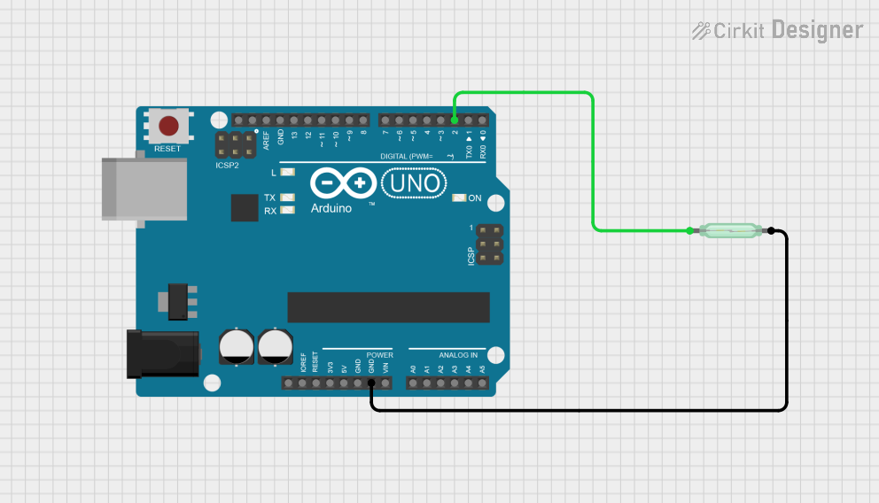
This circuit uses an Arduino UNO to monitor the state of a reed switch. When the reed switch is activated by a magnetic field, the Arduino turns on an onboard LED and outputs a message to the serial monitor. The reed switch is connected to the Arduino with an internal pull-up resistor on digital pin D2, and the LED is controlled via pin D13.
Battery-Powered Arduino Nano Reed Switch LED Indicator
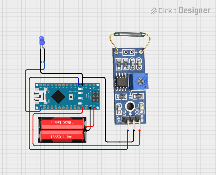
This circuit uses an Arduino Nano to control a blue LED and read input from a reed switch. The Arduino is powered by a 18650 Li-Ion battery, and the reed switch is used to trigger the LED connected to the Arduino's digital pin D13.
Explore Projects Built with LilyPad Reed Switch
Battery-Powered Smart Light with Wemos D1 Mini and Reed Switches
This circuit uses a Wemos D1 Mini microcontroller to monitor the state of multiple reed switches and control a WS2812 RGB LED strip. The microcontroller is powered by a 3xAA battery pack, and the reed switches are used to trigger different actions or lighting patterns on the LED strip.
Wi-Fi Enabled Smart Lid Status Monitor with NodeMCU and RGB LED
This circuit uses a NodeMCU V3 ESP8266 microcontroller to monitor the state of a reed switch and an IR sensor, and control an RGB LED and a piezo buzzer. The microcontroller reads the reed switch state to determine if a lid is open or closed, and it can also read the IR sensor output. The RGB LED is controlled via digital pins D2, D3, and D4, while the piezo buzzer is activated through pin D7.
Arduino UNO Reed Switch Sensor with LED Indicator
This circuit uses an Arduino UNO to monitor the state of a reed switch. When the reed switch is activated by a magnetic field, the Arduino turns on an onboard LED and outputs a message to the serial monitor. The reed switch is connected to the Arduino with an internal pull-up resistor on digital pin D2, and the LED is controlled via pin D13.
Battery-Powered Arduino Nano Reed Switch LED Indicator
This circuit uses an Arduino Nano to control a blue LED and read input from a reed switch. The Arduino is powered by a 18650 Li-Ion battery, and the reed switch is used to trigger the LED connected to the Arduino's digital pin D13.
Common Applications and Use Cases
- Wearable electronics
- Interactive textile projects
- Proximity detection in soft circuits
- Magnetic door or drawer sensors in fabric-based designs
Technical Specifications
Key Technical Details
- Operating Voltage: 3.3V to 5V
- Maximum Switch Current: 0.5A
- Contact Rating: 10W (max)
- Switching Voltage: 100VDC (max)
- Switching Current: 0.5A (max)
Pin Configuration and Descriptions
| Pin Number | Description | Notes |
|---|---|---|
| 1 | S (Signal) | Connects to digital I/O pin |
| 2 | +(Positive) | Connects to VCC (3.3V - 5V) |
| 3 | -(Negative) | Connects to ground (GND) |
Usage Instructions
How to Use the Component in a Circuit
- Sew or connect the
+pin to the VCC of your LilyPad Arduino or compatible microcontroller. - Sew or connect the
-pin to the ground (GND) of your microcontroller. - Sew or connect the
Spin to a digital I/O pin on the microcontroller. - Place a magnet near the reed switch to test its functionality.
Important Considerations and Best Practices
- Ensure that the polarity of the connections is correct to prevent damage.
- Avoid placing the switch near strong electromagnetic fields that could trigger it unintentionally.
- Use a pull-up or pull-down resistor on the signal line to ensure a stable reading when the switch is open.
Example Code for Arduino UNO
// Define the pin connected to the LilyPad Reed Switch
const int reedSwitchPin = 2;

void setup() {
  // Initialize the reed switch pin as an input
  pinMode(reedSwitchPin, INPUT);
  // Begin serial communication at 9600 baud rate
  Serial.begin(9600);
}

void loop() {
  // Read the state of the reed switch
  int switchState = digitalRead(reedSwitchPin);

  // If the switch is closed (magnet is near), print a message
  if (switchState == HIGH) {
    Serial.println("The reed switch is closed.");
  } else {
    Serial.println("The reed switch is open.");
  }

  // Small delay to prevent overwhelming the serial output
  delay(200);
}
Troubleshooting and FAQs
Common Issues Users Might Face
- Switch does not respond: Ensure that the magnet is close enough to the switch and that the switch is properly connected to the microcontroller.
- False triggering: This can occur if the switch is placed near other electronic components that generate a magnetic field. Relocate the switch or shield it from interference.
Solutions and Tips for Troubleshooting
- Check connections: Verify that all connections are secure and correctly polarized.
- Use a multimeter: Check for continuity when the switch is activated to ensure it is functioning.
- Debounce the switch: Implement software debouncing in your code to prevent false triggering due to switch bounce.
FAQs
Q: Can the LilyPad Reed Switch be washed?
- A: Yes, but ensure it is completely dry before powering it up.
Q: How close does the magnet need to be to activate the switch?
- A: The activation distance depends on the strength of the magnet but is typically a few millimeters.
Q: Is it possible to use the reed switch with a battery?
- A: Yes, as long as the battery provides a voltage within the operating range of the switch (3.3V to 5V).