
How to Use ESP32-PoE-ISO: Examples, Pinouts, and Specs
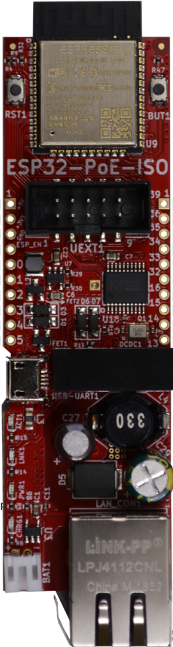
 Design with ESP32-PoE-ISO in Cirkit Designer
Introduction
The ESP32-PoE-ISO, manufactured by Olimex, is a versatile microcontroller board that combines the powerful ESP32 chip with Power over Ethernet (PoE) functionality and galvanic isolation. This integration allows the board to receive both power and data through a single Ethernet cable, simplifying deployment in IoT and industrial applications. The ESP32-PoE-ISO is particularly well-suited for scenarios requiring reliable network connectivity, such as smart home systems, industrial automation, and remote monitoring.
Explore Projects Built with ESP32-PoE-ISO
 Open Project in Cirkit Designer
 Open Project in Cirkit Designer
 Open Project in Cirkit Designer
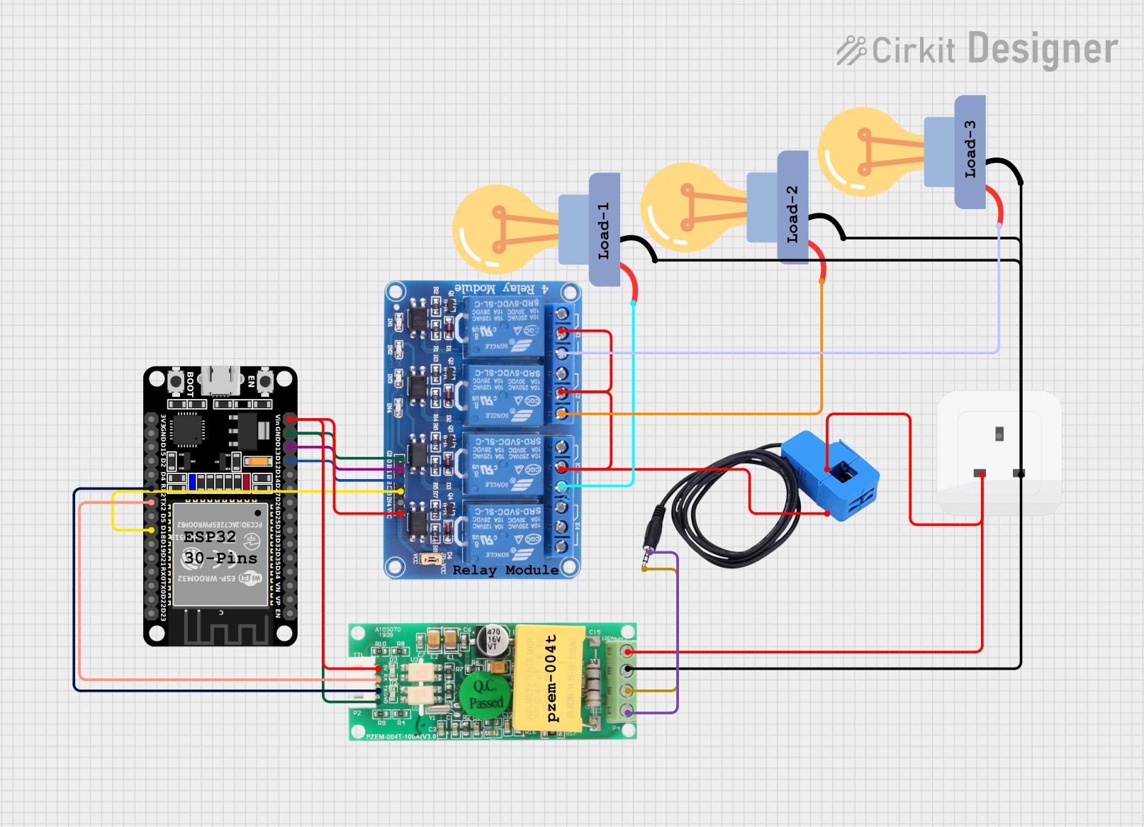 Open Project in Cirkit Designer
Explore Projects Built with ESP32-PoE-ISO
Open Project in Cirkit DesignerOpen Project in Cirkit DesignerOpen Project in Cirkit DesignerOpen Project in Cirkit DesignerCommon Applications
- IoT devices and smart home systems
- Industrial automation and control
- Remote environmental monitoring
- Networked sensors and actuators
- Energy-efficient PoE-powered devices
Technical Specifications
The following table outlines the key technical details of the ESP32-PoE-ISO:
| Parameter | Specification |
|---|---|
| Microcontroller | ESP32 dual-core processor with Wi-Fi and Bluetooth |
| Ethernet | 10/100 Mbps Ethernet with IEEE 802.3af-compliant PoE |
| Isolation | Galvanic isolation between Ethernet PHY and ESP32 |
| Flash Memory | 4 MB |
| RAM | 520 KB |
| Operating Voltage | 3.3V (regulated internally from PoE or external power source) |
| Power Input | PoE (via Ethernet) or external 5V via USB-C |
| GPIO Pins | 26 GPIOs available |
| Communication Interfaces | UART, SPI, I2C, I2S, CAN, PWM, ADC, DAC |
| Dimensions | 57 x 50 mm |
| Operating Temperature Range | -40°C to +85°C |
Pin Configuration and Descriptions
The ESP32-PoE-ISO features a variety of pins for interfacing with peripherals. Below is the pinout description:
| Pin Name | Type | Description |
|---|---|---|
| GPIO0 | Digital I/O | General-purpose I/O, boot mode selection |
| GPIO1 | UART TX | UART transmit pin |
| GPIO3 | UART RX | UART receive pin |
| GPIO12-19 | Digital I/O | General-purpose I/O pins |
| GPIO21 | I2C SDA | I2C data line |
| GPIO22 | I2C SCL | I2C clock line |
| GPIO25-26 | DAC1, DAC2 | Digital-to-analog converter outputs |
| GPIO32-39 | ADC1 Channels | Analog-to-digital converter inputs |
| VIN | Power Input | External 5V power input (via USB-C) |
| GND | Ground | Ground connection |
| ETH_TX/RX | Ethernet | Ethernet transmit and receive pins |
Usage Instructions
How to Use the ESP32-PoE-ISO in a Circuit
Powering the Board:
- Connect the board to a PoE-enabled Ethernet switch or injector to supply power and data through the Ethernet cable.
- Alternatively, power the board via the USB-C connector using a 5V power source.
Programming the ESP32:
- Use the USB-C port to connect the ESP32-PoE-ISO to your computer.
- Install the necessary drivers for the USB-to-serial interface (if required).
- Use the Arduino IDE or ESP-IDF (Espressif IoT Development Framework) to write and upload code to the ESP32.
Connecting Peripherals:
- Use the GPIO pins to interface with sensors, actuators, or other devices.
- Ensure proper voltage levels and isolation when connecting external components.
Networking:
- Configure the Ethernet interface in your code to enable network connectivity.
- Use the built-in Wi-Fi and Bluetooth for wireless communication if needed.
Important Considerations and Best Practices
- Ensure that your Ethernet switch or injector complies with the IEEE 802.3af PoE standard.
- Avoid exceeding the maximum current draw of the board when powering external peripherals.
- Use proper isolation techniques when interfacing with high-voltage or noisy environments.
- When using the board in industrial or outdoor settings, consider additional protection against environmental factors like moisture and dust.
Example Code for Arduino IDE
Below is an example of how to configure the Ethernet interface on the ESP32-PoE-ISO using the Arduino IDE:
#include <ETH.h>

// Define Ethernet configuration
#define ETH_CLK_MODE ETH_CLOCK_GPIO17_OUT  // Use GPIO17 for Ethernet clock
#define ETH_PHY_POWER 12                   // GPIO12 controls Ethernet PHY power

void setup() {
  Serial.begin(115200);
  delay(1000);

  // Initialize Ethernet
  ETH.begin(ETH_CLK_MODE, ETH_PHY_POWER);
  Serial.println("Initializing Ethernet...");

  // Wait for Ethernet connection
  while (!ETH.linkUp()) {
    Serial.println("Waiting for Ethernet connection...");
    delay(1000);
  }

  // Print IP address
  Serial.print("Connected! IP Address: ");
  Serial.println(ETH.localIP());
}

void loop() {
  // Add your main code here
}
Notes:
- Replace
ETH_CLOCK_GPIO17_OUTandETH_PHY_POWERwith the appropriate GPIO pins if using a custom configuration. - Ensure that the Ethernet cable is securely connected to the board and the PoE switch.
Troubleshooting and FAQs
Common Issues and Solutions
No Power via Ethernet:
- Ensure that the Ethernet switch or injector supports IEEE 802.3af PoE.
- Verify that the Ethernet cable is properly connected and not damaged.
Ethernet Connection Fails:
- Check the Ethernet configuration in your code.
- Ensure that the Ethernet PHY power pin (default GPIO12) is correctly set in your code.
Unable to Upload Code:
- Verify that the USB-C cable is functional and supports data transfer.
- Check that the correct COM port is selected in the Arduino IDE or ESP-IDF.
Wi-Fi or Bluetooth Not Working:
- Ensure that the Wi-Fi or Bluetooth functionality is enabled in your code.
- Check for interference or weak signal strength in your environment.
FAQs
Q: Can I use the ESP32-PoE-ISO without PoE?
A: Yes, the board can be powered via the USB-C connector using a 5V power source.
Q: What is the maximum current output for peripherals?
A: The maximum current output depends on the power source (PoE or USB-C) and the load on the board. Ensure not to exceed the PoE power budget or USB power limits.
Q: Is the board compatible with Arduino libraries?
A: Yes, the ESP32-PoE-ISO is compatible with the Arduino IDE and supports most ESP32 libraries.
Q: Can I use both Ethernet and Wi-Fi simultaneously?
A: Yes, the ESP32 supports simultaneous use of Ethernet and Wi-Fi, but proper configuration in your code is required.
This concludes the documentation for the ESP32-PoE-ISO. For further assistance, refer to the official Olimex documentation or community forums.